Supercharge Your Innovation With Domain-Expert AI Agents!

Tip holder

a tip holder and scribe line technology, applied in the field of tip holders, can solve the problem of non-uniform quality of scribe lines

Inactive Publication Date: 2007-09-06
MITSUBOSHI DIAMOND IND CO LTD
View PDF39 Cites 5 Cited by
  • Summary
  • Abstract
  • Description
  • Claims
  • Application Information

AI Technical Summary

Problems solved by technology

This may undesirably result in the quality of the scribe lines being non-uniform.

Method used


Image

  • Tip holder
  • Tip holder
  • Tip holder

Examples


Embodiment Construction

[0046] Hereinafter, the present invention will be described by way of illustrative examples with reference to the accompanying drawings.

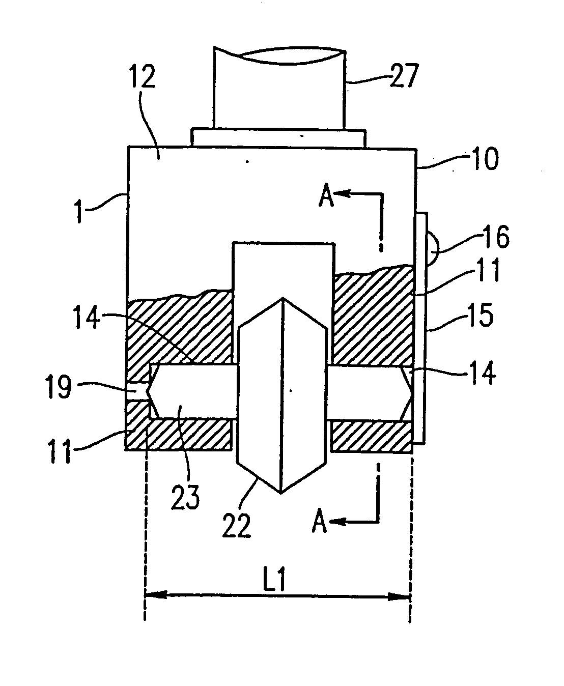
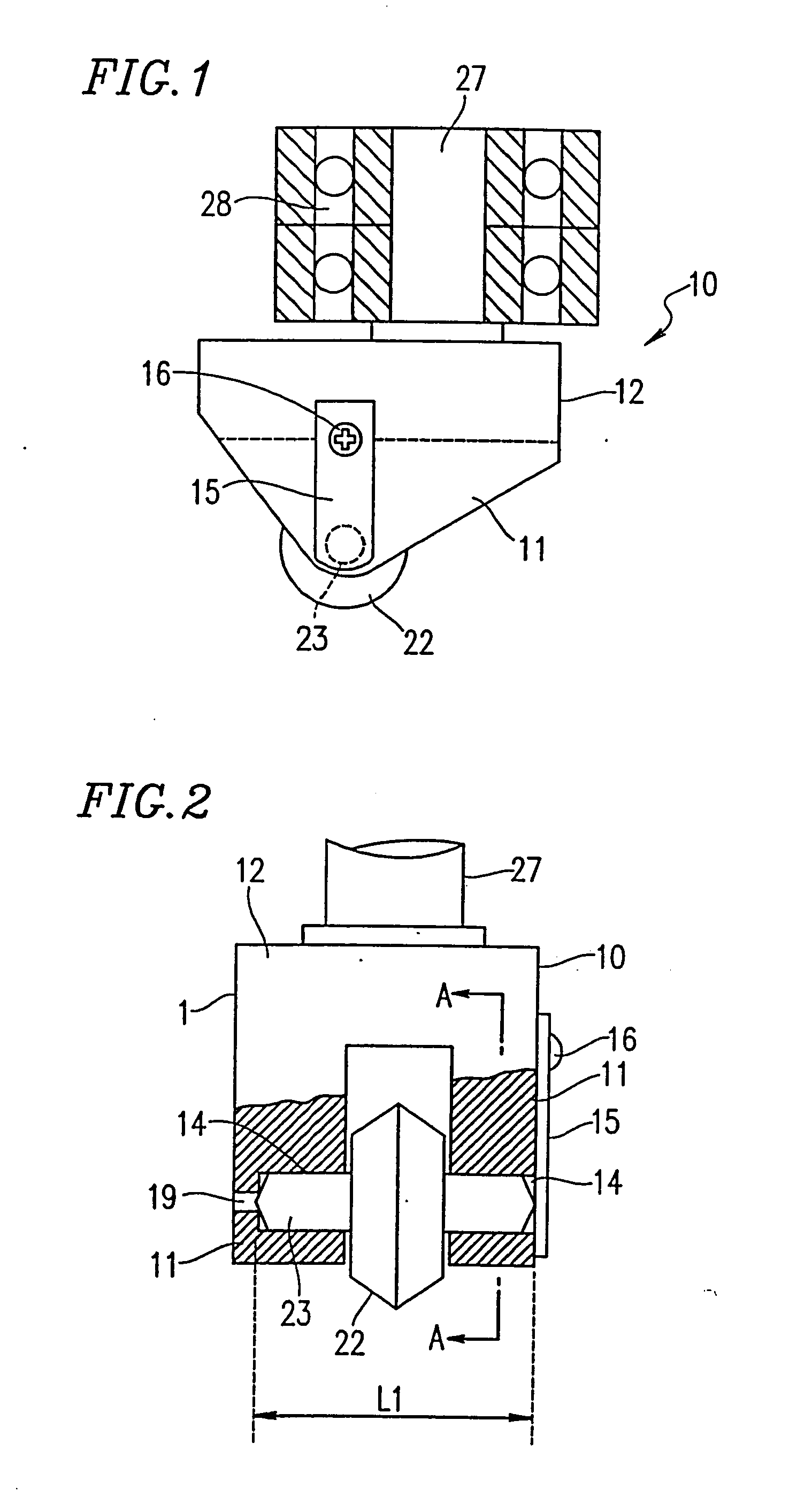
[0047]FIG. 1 is a partially cut side view of a wheel cutter 1 including a tip holder 10 according to one example of the present invention, and FIG. 2 is a partially cut front view of the wheel cutter 1. The wheel cutter 1 includes a cutter wheel tip 22 used for scribing a brittle object such as, for example, a glass plate, and the tip holder 10 for holding the cutter wheel tip 22.

[0048] The cutter wheel tip 22 is circular, has an outer circumferential surface, and is formed of a hard metal, sintered diamond or the like. A center of the entire outer circumferential surface is projecting in such a manner so as to have an obtuse angle and acts as a blade edge.

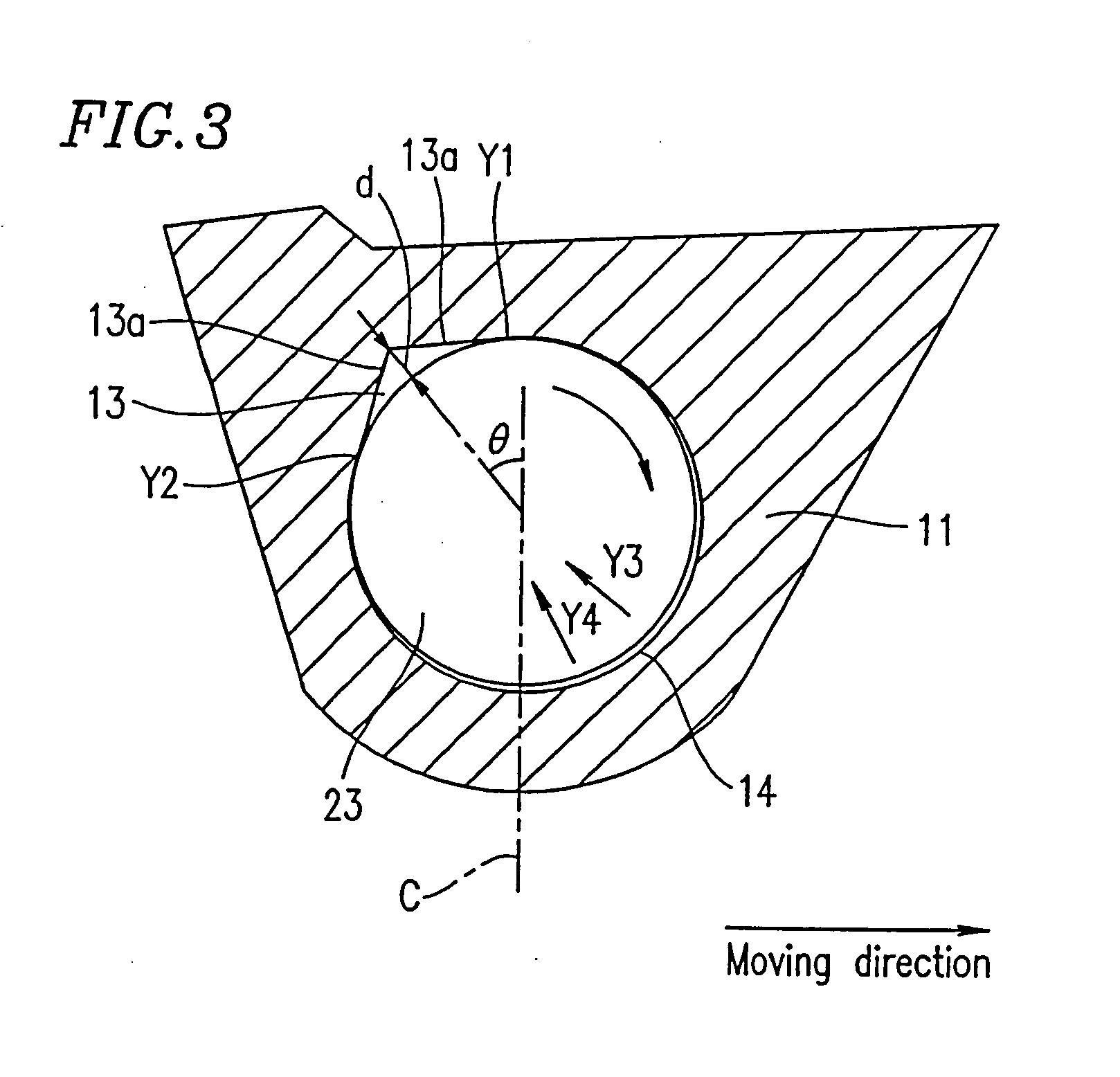
[0049] The cutter wheel tip 22 has a hole at an axial center thereof, and a rotating shaft 23 is passed through the hole. The hole has a diameter which is slightly larger than the diameter of t...


PUM

PropertyMeasurementUnit
angleaaaaaaaaaa
angleaaaaaaaaaa
angleaaaaaaaaaa

Abstract

A rotating shaft (23) is inserted through an axial center of a cutter wheel tip for scribing a brittle object. The rotating shaft (23) is integrally provided with the cutter wheel tip. The rotating shaft (23) is inserted into supporting holes (14) provided in side walls (11) of a tip holder (11) so as to be supported. A groove (13) is formed in an upper portion of each supporting hole (14) along an axial direction of the supporting hole (14).

Description

[0001] This application is a division of copending U.S. application Ser. No. 10 / 433,708, filed Jun. 4, 2003, the entire disclosure of which is incorporated herein by reference.TECHNICAL FIELD OF THE INVENTION [0002] The present invention relates to a tip holder for holding a cutter wheel tip in a wheel cutter used, for example, for scribing or scoring brittle materials such as, glass, for example. BACKGROUND OF THE INVENTION [0003] A glass plate used for a liquid crystal display panel or the like is usually produced by first scribing a large mother glass plate with a wheel cutter so as to form scribe lines, and then cutting the mother glass plate along the scribe lines into pieces of a prescribed size. The wheel cutter includes a circular cutter wheel tip held by a tip holder. [0004] The cutter wheel tip is circular, has an outer circumferential surface, and is formed of a hard metal, sintered diamond or the like. A center of the entire outer circumferential surface projects in such...

Claims


Application Information

Patent Timeline
Patent Type & Authority Applications(United States)
IPC IPC(8): B26D1/12C03B33/027B28D1/22B31B50/25C03B33/10
CPCB28D1/225C03B33/107C03B33/10C03B33/027Y10T83/9377Y10T83/9464Y10T83/0385Y10T83/037Y10T83/9457
Inventor SOYAMA, HIROSHI
Owner MITSUBOSHI DIAMOND IND CO LTD
Features
  • R&D
  • Intellectual Property
  • Life Sciences
  • Materials
  • Tech Scout
  • Unparalleled Data Quality
  • Higher Quality Content
  • 60% Fewer Hallucinations
Learn More