Flow directed guidewire

Active Publication Date: 2008-04-24
HOGANSON DAVID M +1
View PDF51 Cites 17 Cited by
  • Summary
  • Abstract
  • Description
  • Claims
  • Application Information

AI Technical Summary

Benefits of technology

[0018]In accordance with another aspect of this invention, the sail construct may be collapsed or expanded by forces other than flow within the lumen of the vessel, duct, or lumen or contact with the wall or other material within the vessel, duct or lumen. The sail may be collapsible by a number of different methods including but

Problems solved by technology

As described above, orientating a guidewire into the lumen of a narrowing or stenosis of a vessel, duct, or lumen is oft

Method used


Image

  • Flow directed guidewire
  • Flow directed guidewire
  • Flow directed guidewire

Examples


Embodiment Construction

[0054]Before the constructs are described, it is to be understood that this invention is not intended to be limited to the particular constructs and methods described in the preferred embodiments, as one skilled in the art can extend the concepts involved using variations which are obvious after reading the present disclosure.

[0055]It must be noted that, as used in this specification and the appended claims, the singular forms “a”, “an”, and “the” include plural referents, unless the context clearly dictates otherwise.

[0056]Unless defined otherwise, all technical and scientific terms used herein have the same meaning as commonly understood by one of ordinary skill in the art to which this invention belongs. Although any methods and materials similar or equivalent to those described herein may be useful in the practice or testing of the present invention, preferred compositions, films, methods and materials are described below.

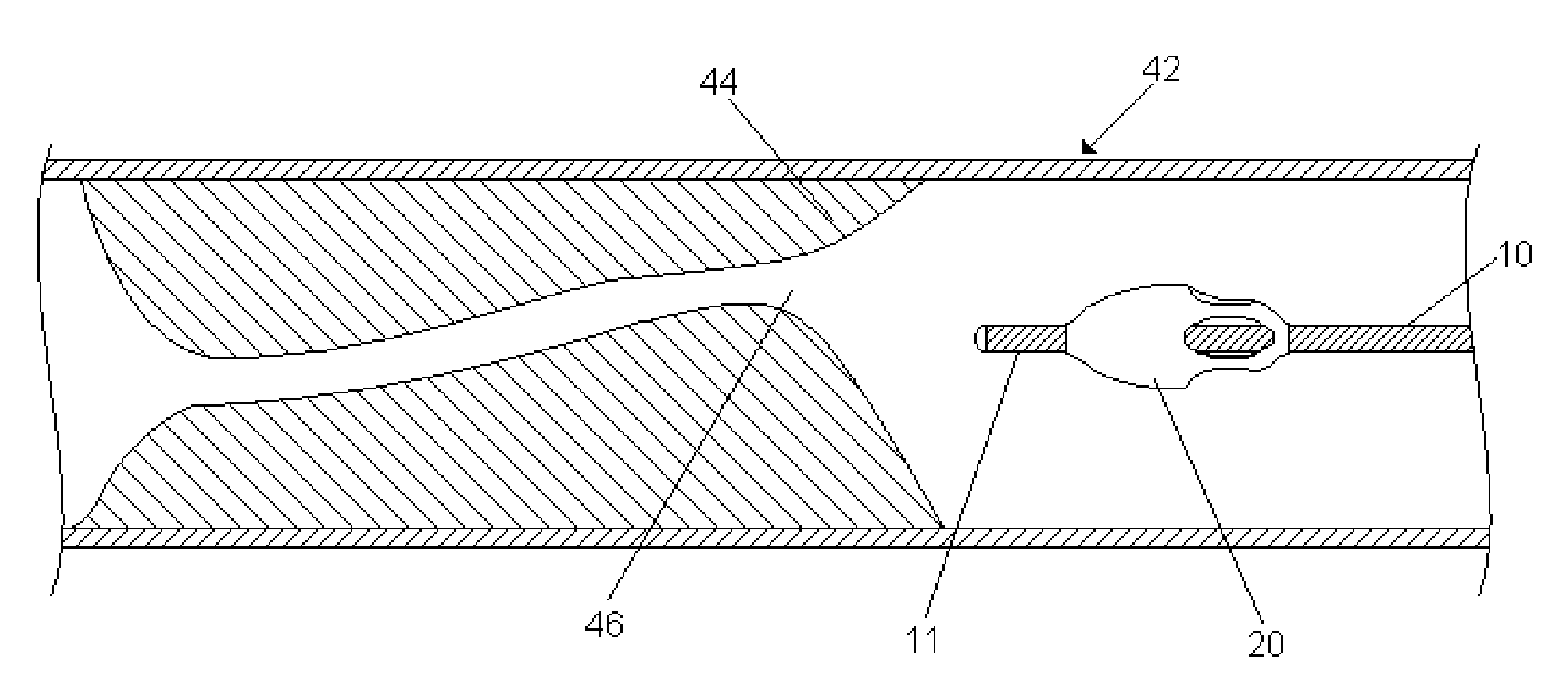
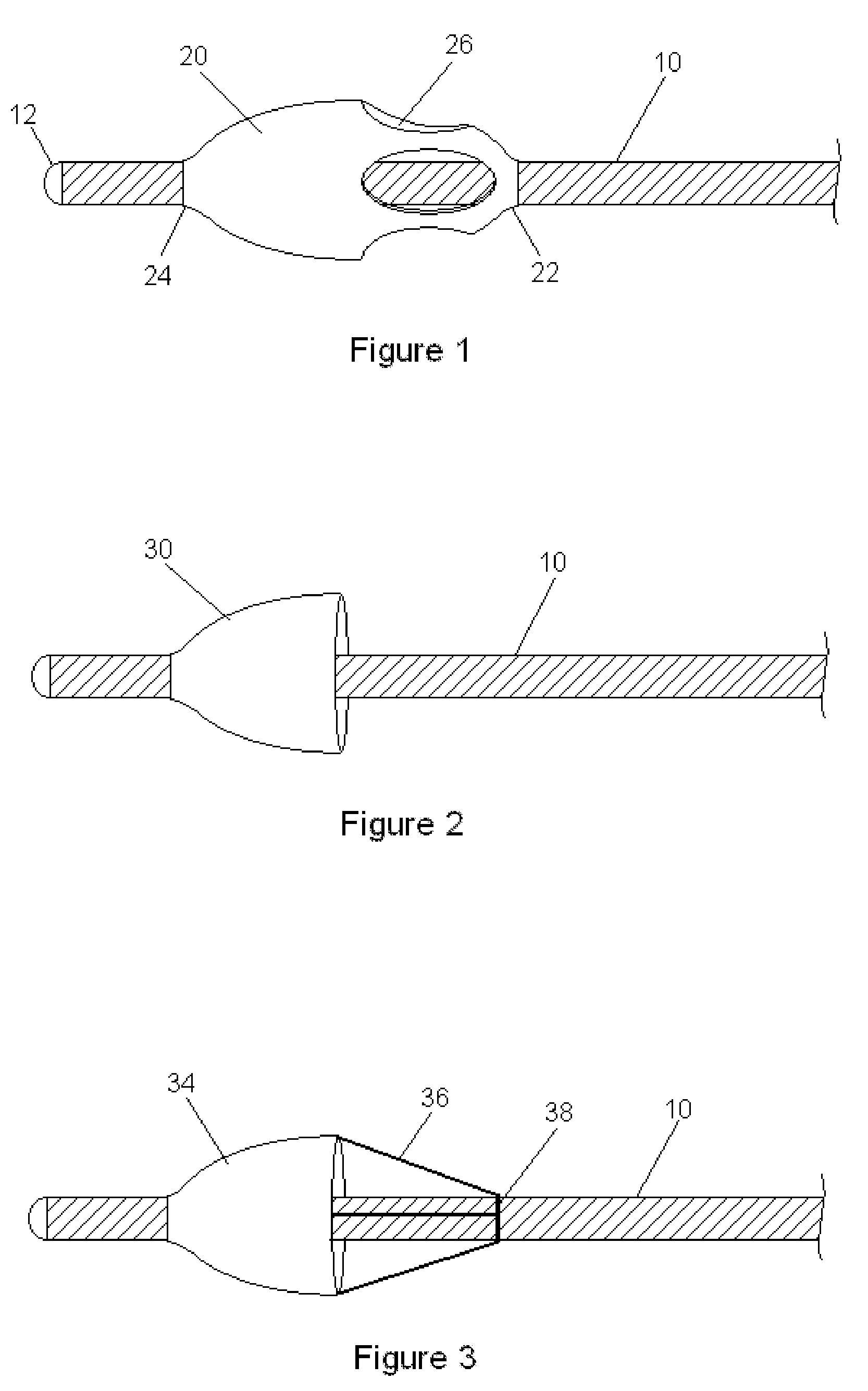
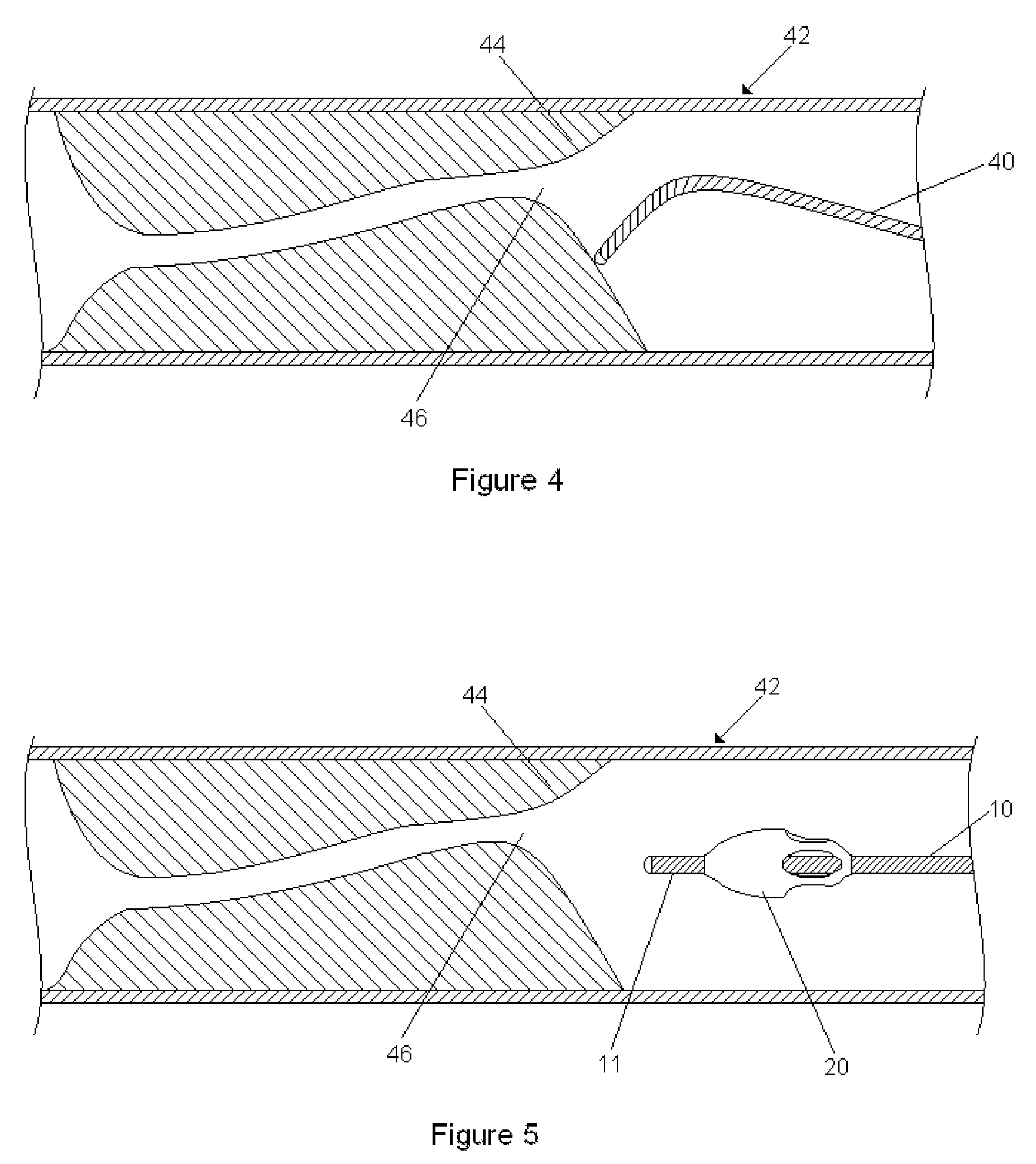
[0057]A preferred embodiment is shown in FIG. 1 where a g...


PUM


Abstract

A device for accessing a vessel, duct or lumen, comprising a guidewire having a proximal end and a distal end, and at least one projection that extends from said guidewire at or near the distal end of the guidewire. When the guidewire is placed into the vessel, duct or lumen containing a flowing fluid, the drag on the guidewire is greater when the fluid is flowing from the proximal to distal end of the guidewire than it is when it is flowing distally-to-proximally, thereby helping to direct the guidewire. The device is particularly useful in crossing a narrowing in the vessel, duct or lumen, such as may occur in blood vessels containing a stenosis, such as due to atherosclerosis.

Description

BACKGROUND OF THE INVENTION[0001]1. Field of the Invention[0002]The instant invention pertains to flow-directed guidewires and catheters, and in particular, to flow-directed guidewires useful for traversing a stenosis in a blood vessel.[0003]2. Discussion of Related Art[0004]Despite advances in guidewire and catheter technology, high-grade stenoses in the coronary or peripheral vasculature continue to pose a considerable challenge. Even experienced interventionalists can expend significant time, effort and resources in crossing these lesions. Furthermore, multiple, failed attempts at traversing a lesion can increase the risk of distal embolization which may have significant implications in some vascular beds. Numerous modifications to guidewires have attempted to increase the efficiency of crossing stenotic areas. For example, hydrophilic coatings, varying degrees and lengths of “floppiness”, and different shapes on the wire tip have all been utilized to facilitate this process. The...

Claims


Application Information

Patent Timeline
IPC IPC(8): A61M25/09
CPCA61M25/0125A61M2025/09175A61M25/09A61B5/6851A61B17/12022
Inventor HOGANSON, DAVID M.VEERASWAMY, RAVI K.
Owner HOGANSON DAVID M
Why Eureka
Try Eureka