Supercharge Your Innovation With Domain-Expert AI Agents!

Computer enclosure

a computer enclosure and bracket technology, applied in the field of computer enclosures, can solve the problems of inefficient assembly and disassembly of the computer enclosure, unduly laborious and time-consuming, and the bracket in the computer enclosure needs extra operating space,

Inactive Publication Date: 2008-05-22
HONG FU JIN PRECISION IND (SHENZHEN) CO LTD +1
View PDF18 Cites 19 Cited by
  • Summary
  • Abstract
  • Description
  • Claims
  • Application Information

AI Technical Summary

Benefits of technology

[0007]A computer enclosure includes a chassis and a bracket secured in the chassis. The chassis includes a bottom plate, a side plate and a rear plate perpendicularly connected with each other. The side plate defines a first mounting slot and a second mounting slot. A pole is disposed on the bottom plate. The bracket defines a post being capable of sliding into the first mounting slot and a bent piece capable of inserting into the second mounting slot. The bracket is supported on the pole of the bottom plate.

Problems solved by technology

Fixing the bracket in the computer enclosure with bolts is unduly laborious and time-consuming.
Furthermore, the computer enclosure needs extra operating space for carrying out the fixing operation.
Since components of a computer are compactly arranged in the computer enclosure, the assembly and disassembly thereof is complicated and inefficient.
Moreover, the components may be accidentally damaged.
This leads to extra maintenance because of plastic rails more easily wear out and need replacement.

Method used


Image

  • Computer enclosure
  • Computer enclosure
  • Computer enclosure

Examples


Embodiment Construction

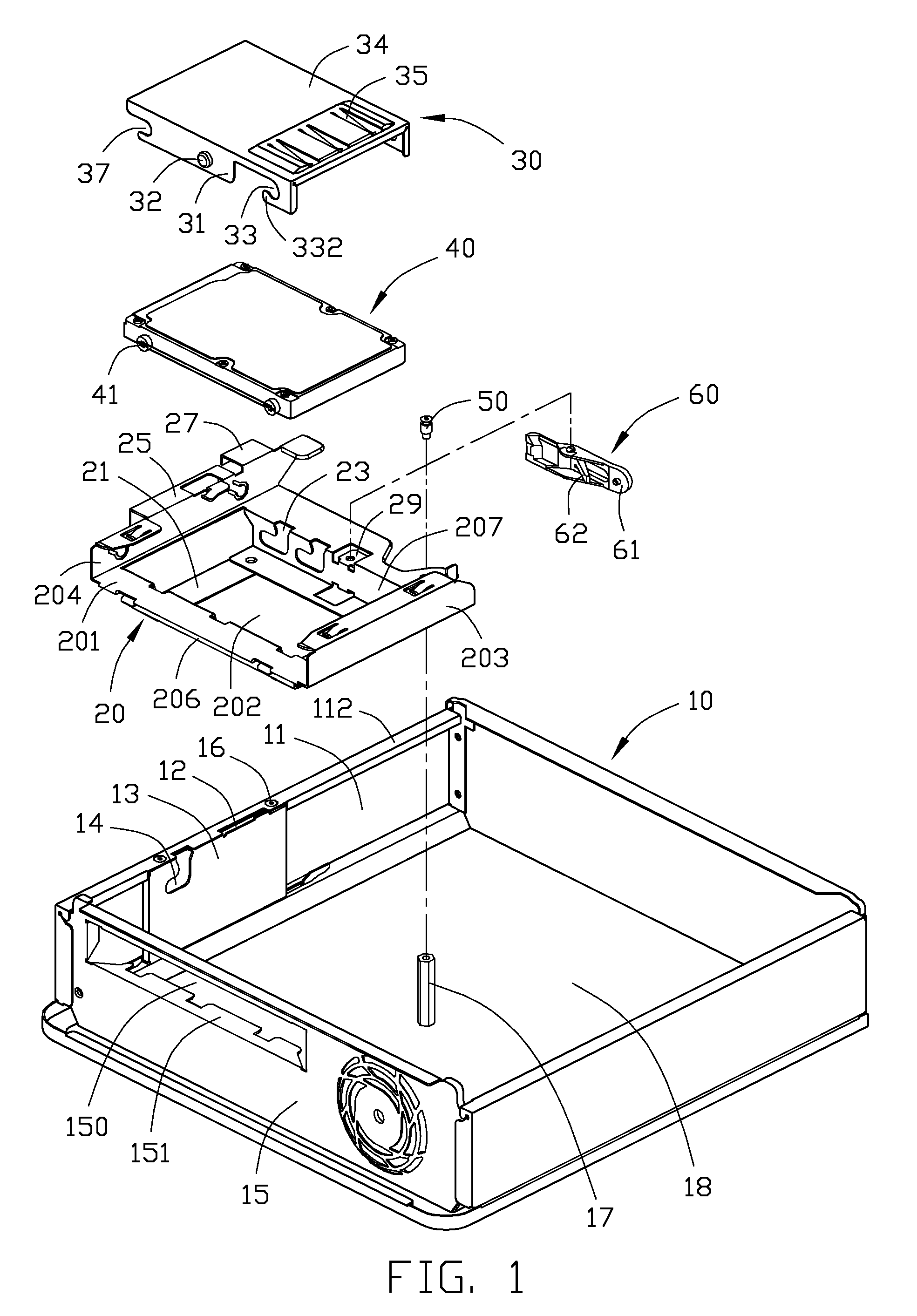
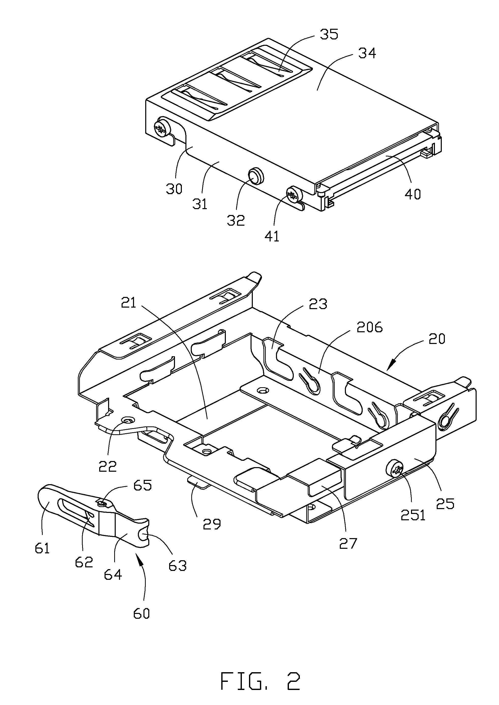
[0013]Referring to FIG. 1, a computer enclosure of a preferred embodiment of the present invention includes a chassis 10, a bracket 20, a tray 30, and a locking member 60.

[0014]The chassis 10 includes a bottom plate 18, a side plate 11, and a rear plate 15. The side plate 11 and the rear plate 15 are perpendicular to each other, and respectively perpendicular to the bottom plate 18. A pole 17 with a mounting hole defined therein is disposed on an inner surface of the bottom plate 18. A rectangular opening 150 is defined in the rear plate 15. A support piece 151 is perpendicularly bent in from a bottom edge of the opening 150. A bent flange 112 is perpendicularly bent in from a top edge of the side plate 11. A securing piece 13 is fixed on an inner surface of the side plate 11 below the bent flange 112 with screws 16. An L-shaped latch slot 14 and a locking slot 12 are defined in the bent flange 112 of the side plate 11 and the securing piece 13. The latch slot 14 includes a horizont...


PUM


Abstract

A computer enclosure includes a chassis (10) and a bracket (20) secured in the chassis. The chassis includes a bottom plate (201), a side plate (11) and a rear plate (15) perpendicularly connected with each other. The side plate defines a first mounting slot (14) and a second mounting slot (12). A pole (17) is disposed on the bottom plate. The bracket defines a post (251) being capable of sliding into the first mounting slot and a bent piece (27) capable of inserting into the second mounting slot. The bracket is supported on the pole of the bottom plate.

Description

[0001]This application is related to co-pending U.S. patent application Ser. No. 11 / 681,195, filed on Mar. 2, 2007, and entitled “COMPUTER ENCLOSURE UTILIZING A MOUNTING APPARATUS”. The present application and the co-pending application are assigned to the same assignee. The disclosure of the above-identified application is incorporated herein by reference.BACKGROUND OF THE INVENTION[0002]1. Field of the Invention[0003]The present invention relates to computer enclosures, and more particularly to a computer enclosure with a bracket for a disk drive of a computer or a server.[0004]2. Description of Related Art[0005]Disk drives, such as an HDD (hard disk drive) and a CD-ROM (compact disc read-only memory) drive, are usually provided in a computer. Conventionally, the disk drives are secured in a bracket. The bracket is fixed on a chassis of a computer enclosure by bolts or rails. Fixing the bracket in the computer enclosure with bolts is unduly laborious and time-consuming. Furthermor...

Claims


Application Information

Patent Timeline
Patent Type & Authority Applications(United States)
IPC IPC(8): A47B96/00
CPCG06F1/187
Inventor CHEN, YUN-LUNGXIAO, YU-MING
Owner HONG FU JIN PRECISION IND (SHENZHEN) CO LTD
Features
  • R&D
  • Intellectual Property
  • Life Sciences
  • Materials
  • Tech Scout
  • Unparalleled Data Quality
  • Higher Quality Content
  • 60% Fewer Hallucinations
Learn More