Optical fiber and method of manufacturing the same
a technology of optical fiber and manufacturing method, applied in the field of optical fiber, can solve the problems of double refraction, uncircularized portion, etc., and achieve the effect of preventing deterioration of good polarization mode dispersion characteristic, and suppressing continuity in longitudinal direction
- Summary
- Abstract
- Description
- Claims
- Application Information
AI Technical Summary
Benefits of technology
Problems solved by technology
Method used
Image

Examples
first embodiment
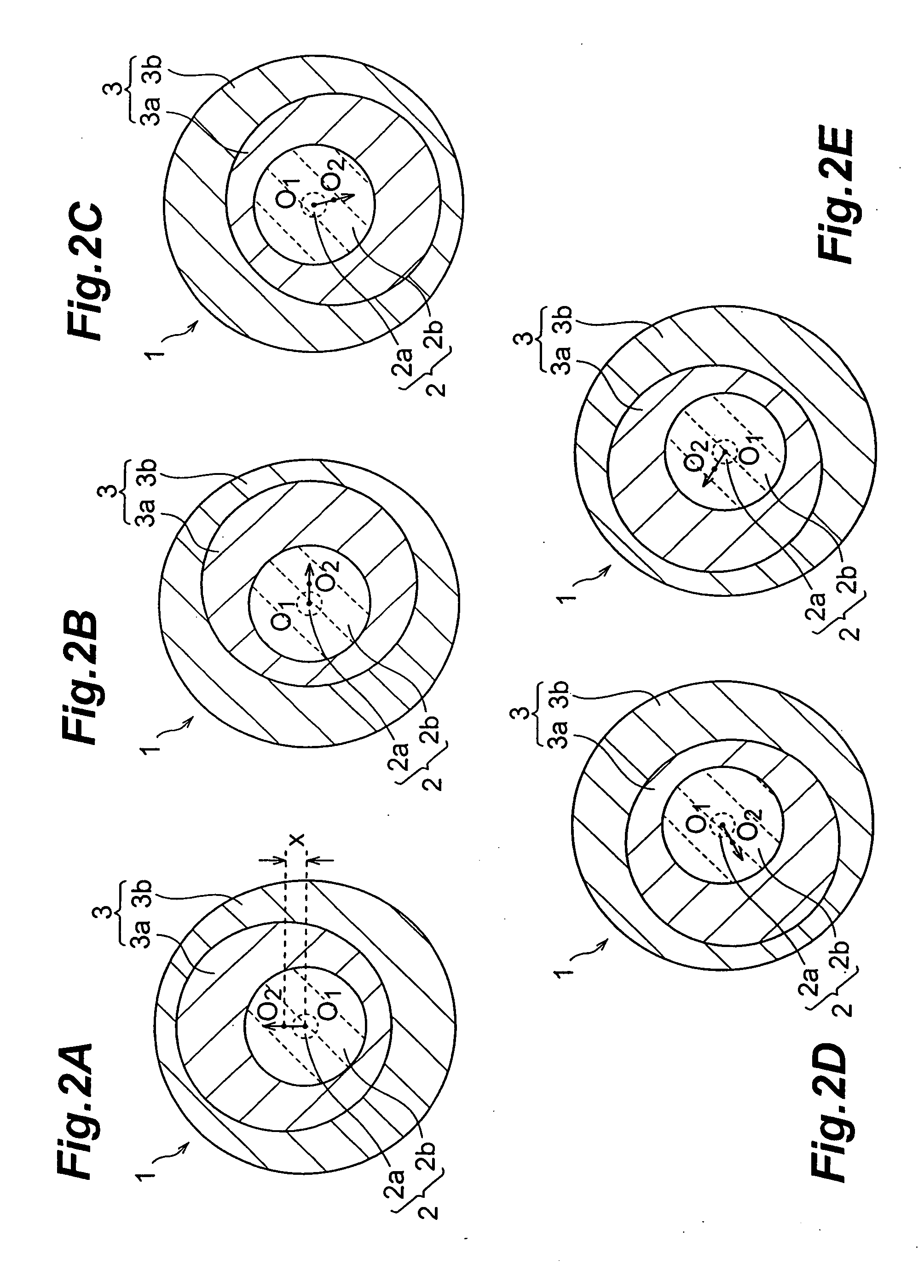
[0027]The optical fiber 1 of this embodiment comprises a glass portion 2 including a core 2a having a high refractive index and a cladding 2b having a low refractive index, which is formed around the core 2a, and a covering layer 3, which is composed of an internal covering layer 3a having a low Young's modulus and an external covering layer 3b having a high Young's modulus. An external diameter of the glass portion 2 is 125 μm, an external diameter of the internal covering layer 3a ranges from 170 to 200 μm, and an external diameter of the external covering layer 3b ranges from 235 to 265 μm. Any of the internal and external covering layers 3a and 3b is a resin covering layer using ultra violet-curing resin. The glass portion 2, the internal covering layer 3a and the external covering layer 3b assume a circular shape on a section (transverse plane) perpendicular to the longitudinal direction (extending direction) of the optical fiber 1, the circular shape having an out-of-roundness...
second embodiment
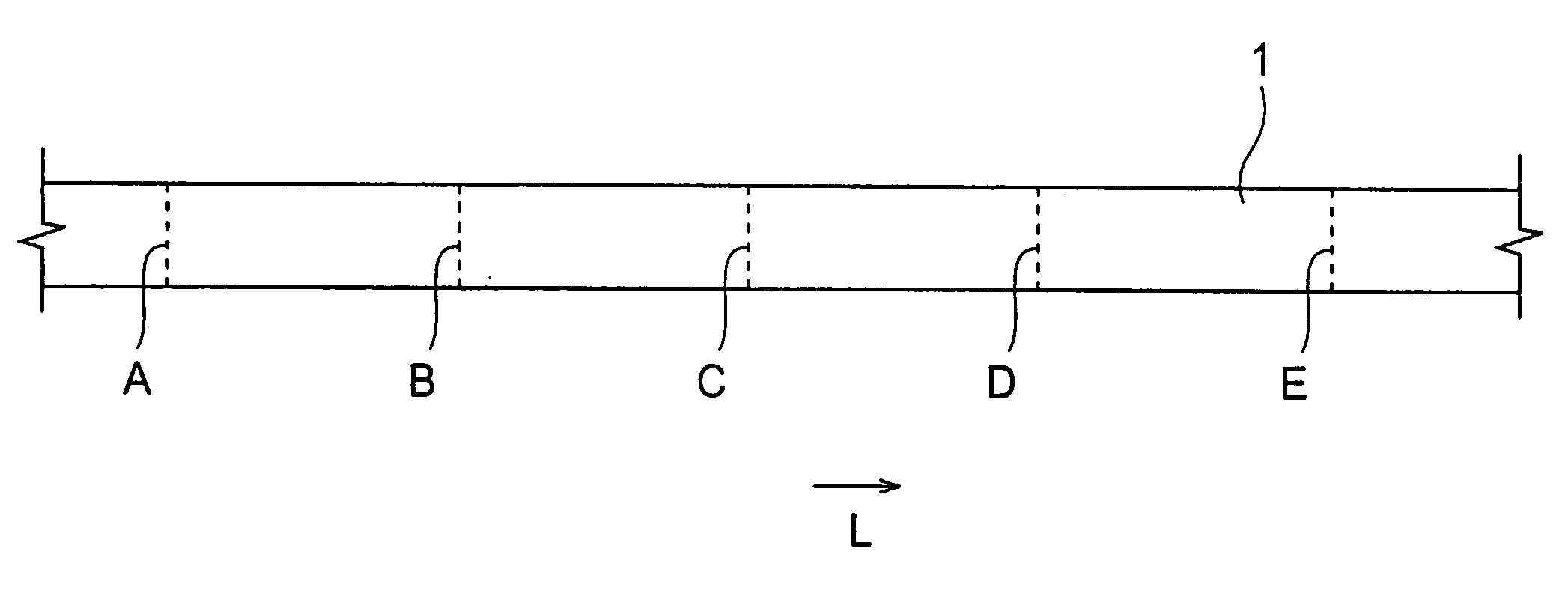
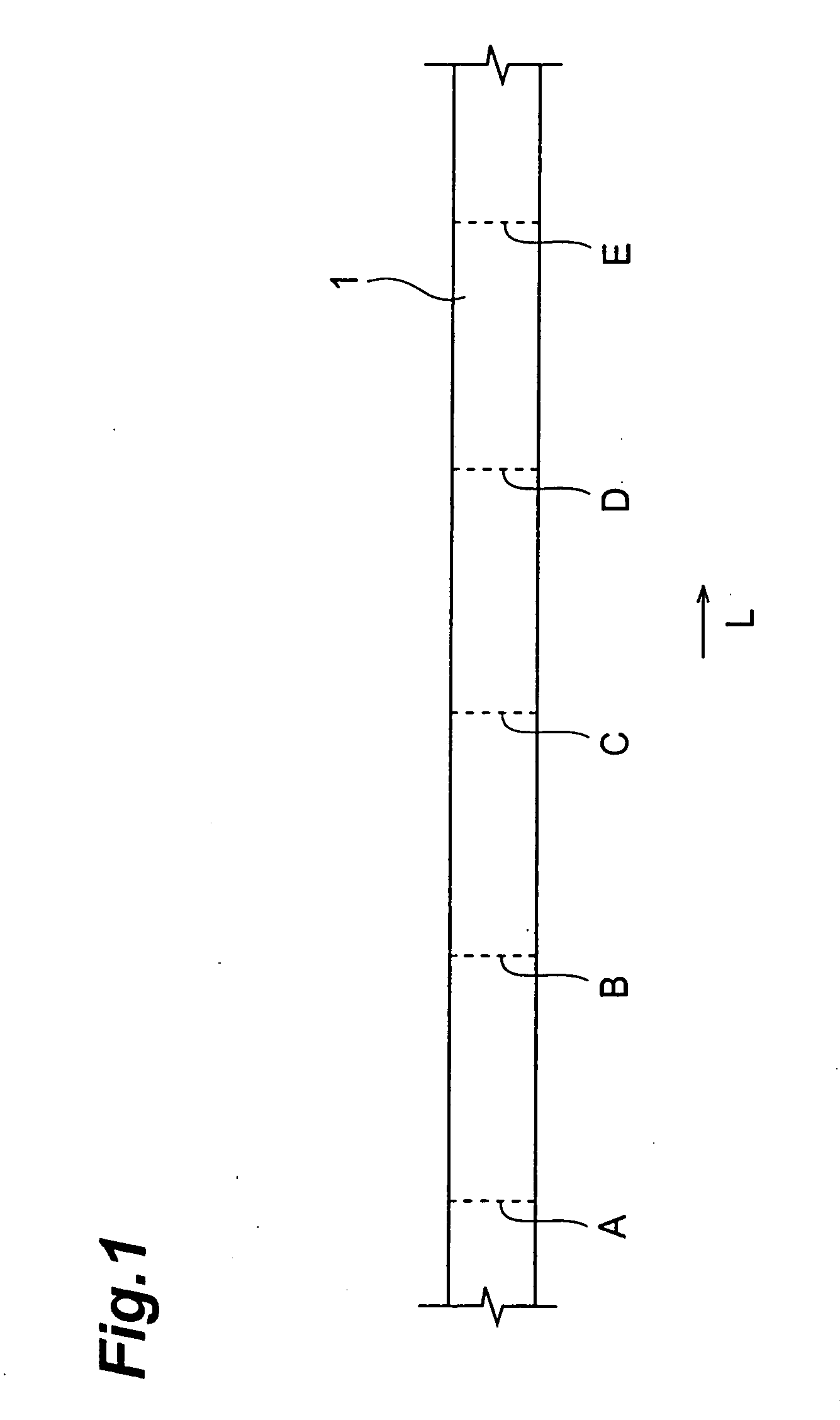
[0032]In this embodiment, as shown in FIGS. 3A to 3E, the center of the glass portion 2 and the center of the internal covering layer 3a are approximately coincident with each other as the center O1. On the contrary, the center O2 of the external covering layer 3b is decentered from the center O1. The decenter direction (arrow direction in FIGS. 3A to 3E) is changed in the longitudinal direction of the optical fiber 1. Particularly, in this embodiment, the decenter direction is rotated in a certain direction (clockwise in FIGS. 3A to 3E) along the longitudinal direction (direction of the arrow L in FIG. 1) of the optical fiber 1.
[0033]Since the glass portion 2 and the external covering layer 3b are decentered from each other in the optical fiber 1 of this embodiment, the continuity in the longitudinal direction of the stress vector applied to the optical fiber 1 is consequently controlled. Also with such a configuration, similarly to the foregoing first embodiment, deterioration of ...
third embodiment
[0037]In this embodiment, as shown in FIGS. 4A to 4E, the outer peripheral shape of the internal covering layer 3a in cross section (perpendicular to the longitudinal direction of the optical fiber 1), that is, the shape of the boundary surface between the internal covering layer 3a and the external covering layer 3b, is uncircularized. “Uncircularize” means that the shape is intentionally made not to be a perfect circle. Specifically, the out-of-roundness of the outer periphery of the internal covering layer 3a in cross section is intentionally made to be large on the cross section perpendicular to the longitudinal direction of the optical fiber 1. Herein, the out-of-roundness is defined as a difference between the maximum diameter of an inscribed circle and the minimum diameter of a circumscribed circle. In this embodiment, the outer peripheral shape of the internal covering layer 3a in cross section is made to be elliptical as one mode of uncircularize.
[0038]The outer peripheral ...
PUM
| Property | Measurement | Unit |
|---|---|---|
| distance | aaaaa | aaaaa |
| diameter | aaaaa | aaaaa |
| diameter | aaaaa | aaaaa |
Abstract
Description
Claims
Application Information
 - R&D
- Intellectual Property
- Life Sciences
- Materials
- Tech Scout
- Unparalleled Data Quality
- Higher Quality Content
- 60% Fewer Hallucinations
Browse by: Latest US Patents, China's latest patents, Technical Efficacy Thesaurus, Application Domain, Technology Topic, Popular Technical Reports.
© 2025 PatSnap. All rights reserved.Legal|Privacy policy|Modern Slavery Act Transparency Statement|Sitemap|About US| Contact US: help@patsnap.com