Tubular body

Inactive Publication Date: 2008-10-30
DAIWA SEIKO CORPORATION
View PDF0 Cites 10 Cited by
  • Summary
  • Abstract
  • Description
  • Claims
  • Application Information

AI Technical Summary

Benefits of technology

[0007]The present invention has been accomplished in view of the foregoing situation and it is an object thereof to provide a tubular body of

Problems solved by technology

In this case, there is a high poss

Method used


Image

  • Tubular body
  • Tubular body
  • Tubular body

Examples


Example

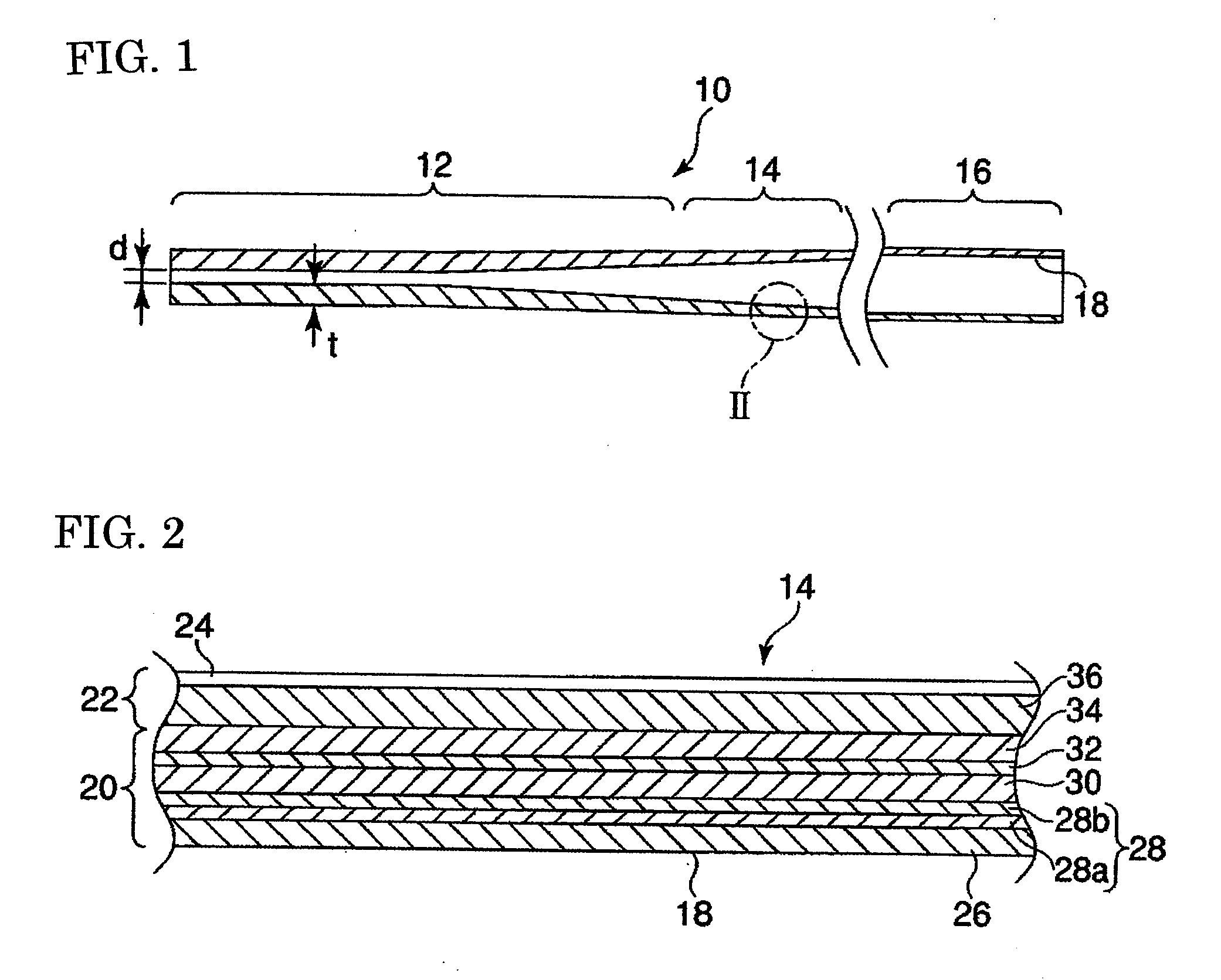
[0037]FIG. 1 shows a tubular body 10 according to a referred embodiment of the invention. In this embodiment, the tubular body is formed as a shaft of a golf club in which the strength and the rigidity have to be increased more with respect to the weight thereof. In addition, the tubular body 10 can be formed also as sport goods such as a fishing rod or a tennis racket.

[0038]The tubular body 10 of this embodiment is formed as a tapered shape toward the top end, that is, to the side of attaching a club head that hits a ball in a case of a golf club shaft. A top part 12, an intermediate part 14, and a base part 16 attached with a grip are formed from the side of the top end, and an inner hole 18 penetrating in the axial direction, that is, the longitudinal direction opens at the top end and the rear end outwardly.

[0039]In the tubular body 10, the thickness t at the top part 12 at a position where a reinforcing lug 44 to be described later is not disposed is made larger than the inner ...


PUM

PropertyMeasurementUnit
Fractionaaaaaaaaaa
Transparencyaaaaaaaaaa

Abstract

A tubular body comprising: a main body layer formed by winding a fiber-reinforced prepreg including reinforcing fibers impregnated with a synthetic resin; and a reinforcing layer wounded around the main body. The reinforcing layer includes: an axial fiber layer including reinforcing fibers aligned in an axial direction of the tubular body; a skew fiber layer formed by aligning a first skew fiber layer formed of reinforcing fibers aligned in a skew direction and a second skew fiber layer formed of reinforcing fibers aligned in a different skew direction; a circumferential fiber layer formed by aligning reinforcing fibers in a circumferential direction of the tubular body. The axial fiber layer, the skew fiber layer and the circumferential fiber are braided with a braiding yarn softer than the reinforcing fibers to form braided prepreg as the reinforcing layer.

Description

BACKGROUND OF THE INVENTION[0001]The present invention concerns a tubular body and, particularly, it relates to a tubular body formed by winding a fiber-reinforced prepreg having reinforcing fibers impregnated with a synthetic resin.[0002]Generally, a tubular body such as a shaft of a golf club is formed as a laminate prepared by winding a fiber-reinforced prepreg having reinforcing fibers impregnated with a synthetic resin so as to overlap a mandrel, winding a tightening tape thereover for stabilization, then heat setting the synthetic resin in a heating furnace, subsequently, cooling the same, and by way of steps such as removal of the mandrel, peeling of the tightening tape, polishing, and coating.[0003]While the tubular body formed of such a fiber-reinforced prepreg is excellent in specific strength and specific rigidity, the property of the tubular body changes greatly depending on the direction and the lamination conditions of the reinforcing fibers.[0004]In view of the above,...

Claims


Application Information

Patent Timeline
IPC IPC(8): B29C70/10B29D23/00A01K87/00A63B53/10A63B102/32
CPCA63B53/10Y10T428/1369B29C53/60B29C70/24B29C70/32B29D23/001B29K2105/12B29L2009/00B29L2023/22B29L2031/5227B29L2031/5245B32B1/08B32B5/28F16L9/123A63B2209/023A63B60/00
Inventor SUZUKI, HIROYUKI
Owner DAIWA SEIKO CORPORATION
Why Eureka
Try Eureka