Check patentability & draft patents in minutes with Patsnap Eureka AI!

Motor, fan, rotor holder and manufacturing method of the same

a technology of motors and rotors, applied in the direction of dynamo-electric machines, structural associations, supports/encloses/casings, etc., can solve the problems of motor vibration generating noise, significant noise may be generated,

Active Publication Date: 2009-01-01
NIPPON DENSAN CORP
View PDF4 Cites 13 Cited by
  • Summary
  • Abstract
  • Description
  • Claims
  • Application Information

AI Technical Summary

Benefits of technology

[0005]By such manufacturing method, it becomes possible to manufacture the rotor holder in an efficient and speedily manner.

Problems solved by technology

When the rotation of the impeller is increased, a significant amount noise may be generated if a weight balance of a rotor assembly including a rotor portion (including the impeller) of the motor with respect to a rotational axis thereof is compromised.
Also, when the rotation of the impeller is increased, the motor may be vibrated generating noise.

Method used


Image

  • Motor, fan, rotor holder and manufacturing method of the same
  • Motor, fan, rotor holder and manufacturing method of the same
  • Motor, fan, rotor holder and manufacturing method of the same

Examples


Embodiment Construction

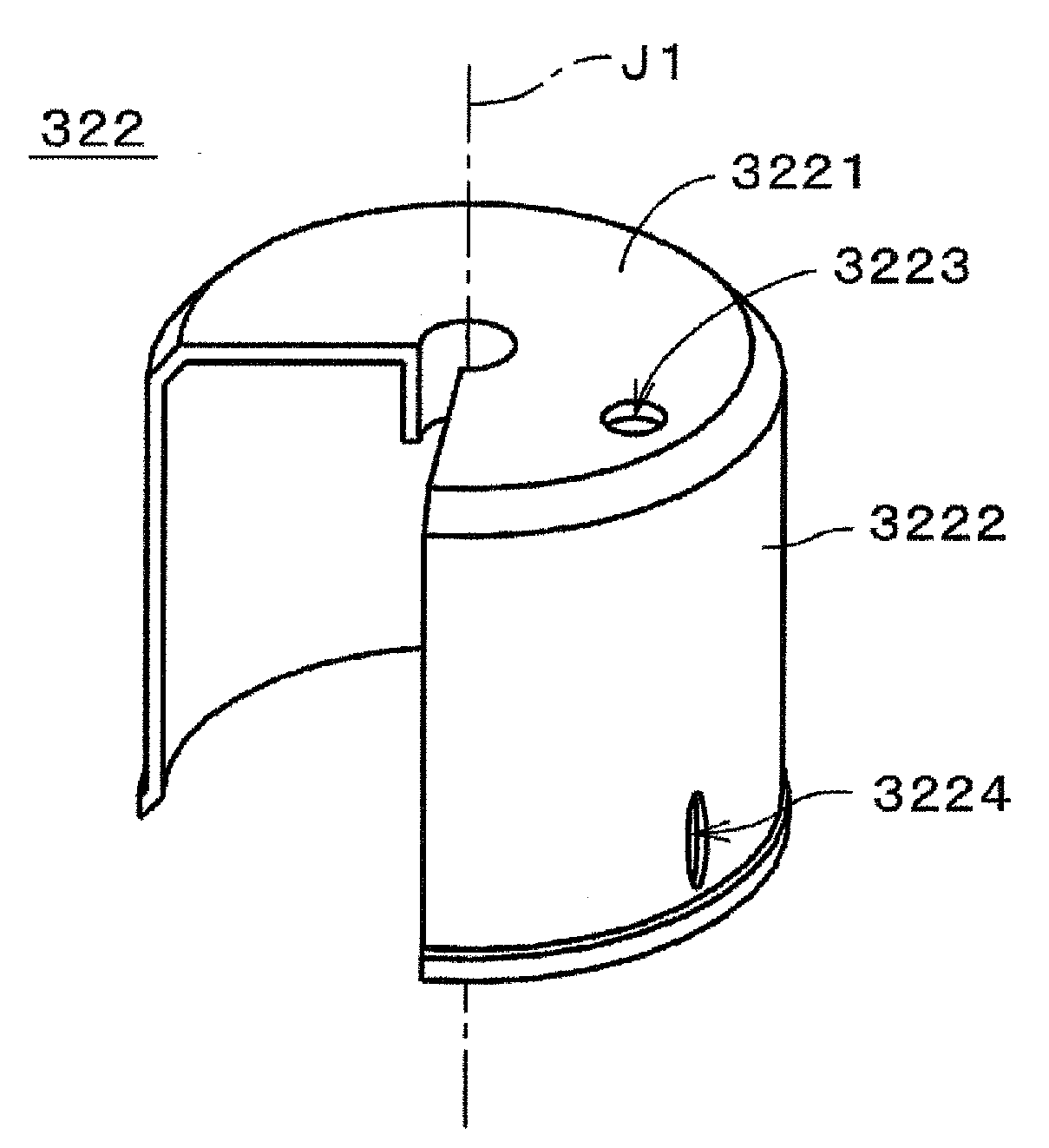
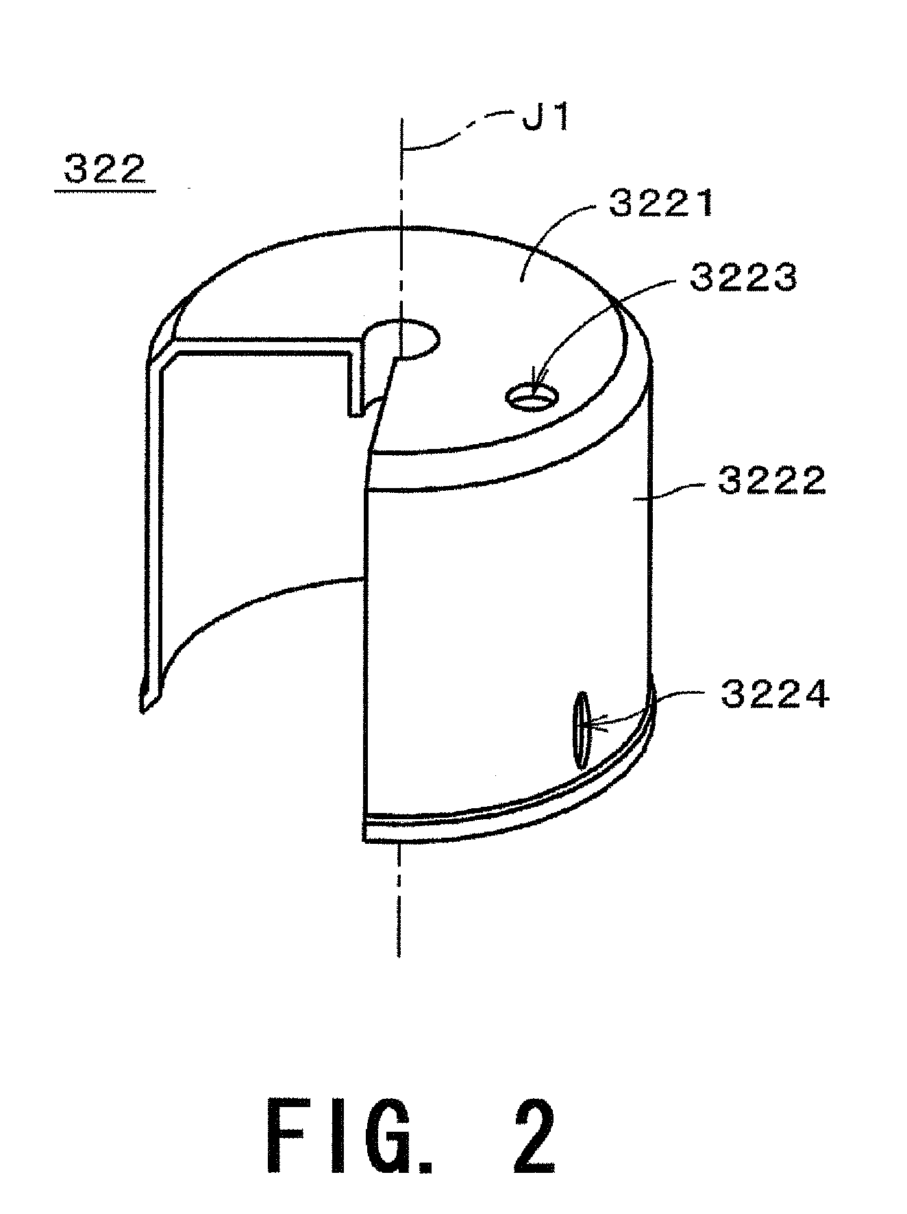
[0025]Note that in the description of preferred embodiments of the present invention herein, words such as upper, lower, left, right, upward, downward, top, and bottom for describing positional relationships between respective members and directions merely indicate positional relationships and directions in the drawings. Such words do not indicate positional relationships and directions of the members mounted in an actual device. Also note that reference numerals, figure numbers, and supplementary descriptions are shown below for assisting the reader in finding corresponding components in the description of the preferred embodiments below to facilitate an understanding of the present invention. It is understood that these expressions in no way restrict the scope of the present invention.

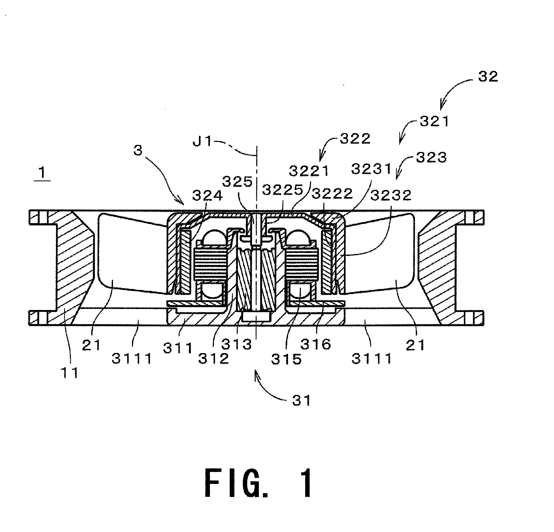
[0026]FIG. 1 is a schematic cross sectional view of a fan 1 according to a first preferred embodiment of the present invention. As shown in FIG. 1, the fan 1 preferably includes a housing 11, a motor...


PUM

PropertyMeasurementUnit
internal diameteraaaaaaaaaa
cylindrical shapeaaaaaaaaaa

Abstract

The manufacturing method of a rotor holder according to the present invention includes a step in which a top plate portion having a substantially discoid shape substantially centered about a central axis, and a side wall portion extending from an outer circumferential edge of the top plate portion are formed simultaneously by feeding a metal plate in a predetermined direction and pressing the metal plate by a die. Also, the present manufacturing method includes a step in which a punched portion is formed at the side wall portion.

Description

FIELD OF THE INVENTION[0001]The present invention relates to a motor, a rotor holder and its manufacturing method. Also, the present invention relates to a fan having the motor including the rotor holder.BACKGROUND OF THE INVENTION[0002]Conventionally, a fan which includes an impeller having a plurality of blades powered by a motor is arranged inside an electronic device so as to cool heated components therein and to let out the heated air of the electronic device. In recent years, due to an increase in the amount of heat generated by the electronic device, the rotation speed of the impeller is increased.[0003]When the rotation of the impeller is increased, a significant amount noise may be generated if a weight balance of a rotor assembly including a rotor portion (including the impeller) of the motor with respect to a rotational axis thereof is compromised. Also, when the rotation of the impeller is increased, the motor may be vibrated generating noise. In particular, the rotor ho...

Claims


Application Information

Patent Timeline
Patent Type & Authority Applications(United States)
IPC IPC(8): H02K5/24H02K15/00
CPCH02K1/2786H02K7/14Y10T29/49012Y10T29/49009H02K15/03H02K1/2791
Inventor HANAOKA, SATORUSUGIYAMA, TOMOTSUGUTABATA, SHINYATSUKADA, TAKASHI
Owner NIPPON DENSAN CORP
Features
  • R&D
  • Intellectual Property
  • Life Sciences
  • Materials
  • Tech Scout
  • Unparalleled Data Quality
  • Higher Quality Content
  • 60% Fewer Hallucinations
Learn More