Check patentability & draft patents in minutes with Patsnap Eureka AI!

Conveyor for sheet-shaped thin plate and method of conveying same

a technology of conveying device and sheet-shaped thin plate, which is applied in the direction of manufacturing tools, soldering devices,auxillary welding devices, etc., can solve the problems of high labor intensity, high time and labor intensity, and inability to achieve good welding conditions, etc., and achieves easy adjustment

Inactive Publication Date: 2009-02-12
SUZUKI MOTOR CORP
View PDF3 Cites 1 Cited by
  • Summary
  • Abstract
  • Description
  • Claims
  • Application Information

AI Technical Summary

Benefits of technology

The system simplifies adjustment, prevents vertical superposition, maintains high welding quality, and reduces deformation and wear, improving the butt-welding performance and adhesion between plates.

Problems solved by technology

Therefore, if the adjustment of guide members provided for the respective conveying members is not made precisely, there may cause an adverse possibility such that the ends to be welded of the thin plates are superposed in the vertical direction, or a gap is created therebetween.
Hence, the good welding condition cannot be expected, thus being inconvenient.
Moreover, since the conveying members are themselves provided for the respective two thin plates, the adjustment therebetween, for example, in positional adjustment, requires much time and labor, including extra working.
Thus, periodical inspection for the relative positional adjustment between two thin plates will be required, thus being inconvenient.
However, since the thin plate must bypass the guide rollers, the deformation amount thereof will be inevitably increased, straightness of a butted surface is made worse, and adhering condition with respect to the thick plate is deteriorated.
In addition, it is necessary to separately provide an additional member for deforming the thin plate into a corrugated shape, and thus, the entire structure of the apparatus will become complicated.
As a result, resistance is generated when the thin plate is deformed into the corrugated shape and this adversely affects the conveying operation, which may cause a fear such that the conveying speed becomes unstable.
In addition, there is a further adverse possibility that a contact area between the guide surface of the guide roller and the thick plate is increased, the conveying resistance is increased due to the slide contact therebetween, and the wearing is hence increased.
Furthermore, it is necessary to chamfer the guide surface of the guide roller to prevent the biting between the guide surface of the guide roller and the thick plate, which may result in that the deformation amount of the thin plate is increased by the chamfered amount, the straightness of the butted surface is made worse, and the adhesion to the thick plate is deteriorated.

Method used


Image

  • Conveyor for sheet-shaped thin plate and method of conveying same
  • Conveyor for sheet-shaped thin plate and method of conveying same
  • Conveyor for sheet-shaped thin plate and method of conveying same

Examples


Embodiment Construction

[0051]Hereunder, a preferred embodiment of the present invention will be explained with reference to the accompanying drawings. Further, it is to be noted that terms “upper”, “lower”, “right”, “left” and the like terns are used herein with reference to the illustrated state on the drawings or in a usually operative state of the apparatus.

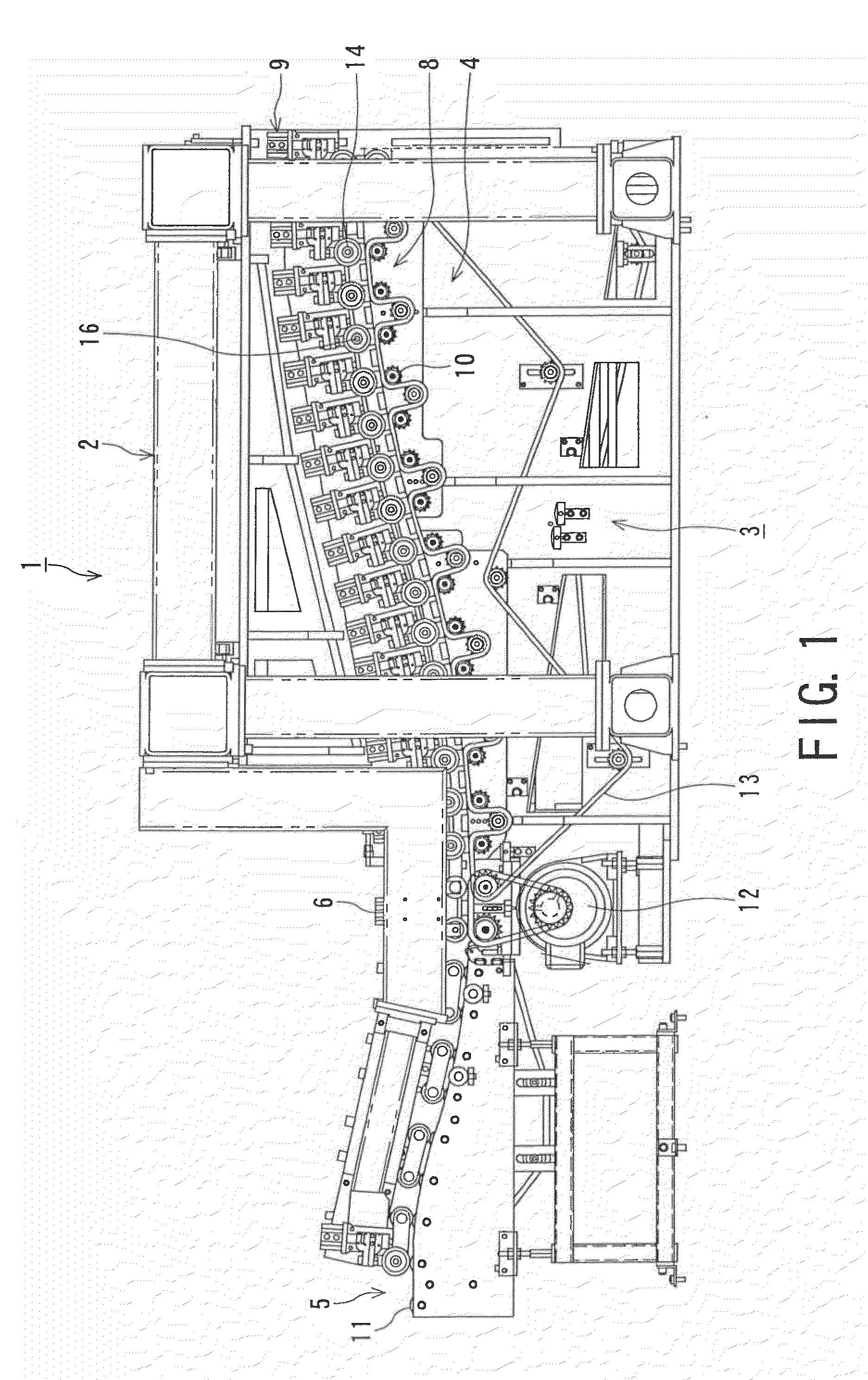
[0052]FIG. 1 shows a continuous welding apparatus to which a conveyor for a sheet-shaped thin plate of the present invention is applicable (which may be called hereinafter “sheet-shaped thin plate conveyor” or merely “conveyor”).

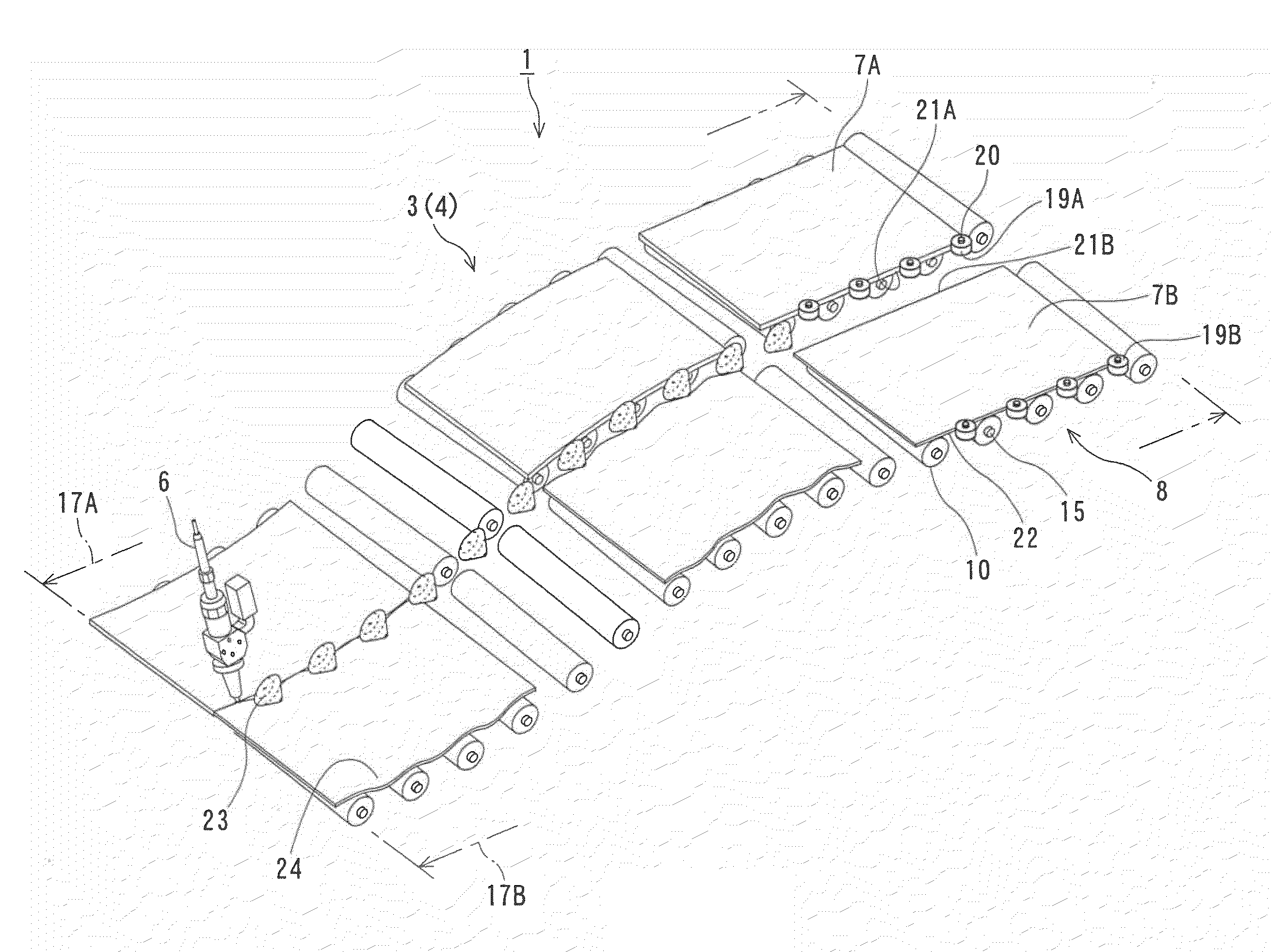
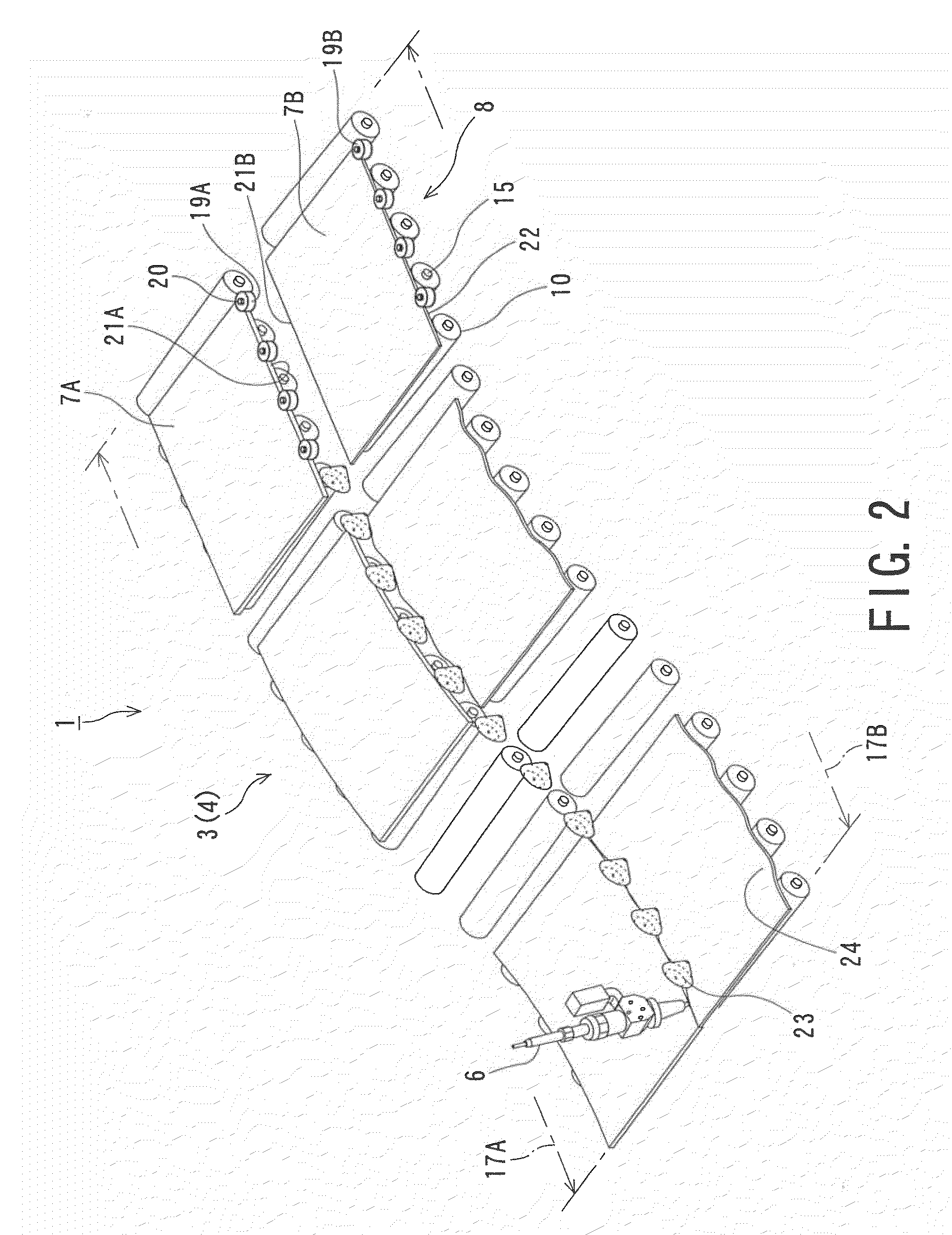
[0053]As shown in FIG. 1, the continuous welding apparatus or machine 1 includes a sheet-shaped thin plate conveyor 3 assembled to a framework 2. The conveyor 3 mainly includes a carry-in unit 4 and a carry-out unit 5 for the sheet-shaped thin plates.

[0054]In this embodiment, a fixed laser welding machine 6 is used as welding means. The laser welding machine 6 is disposed above and between the carry-in unit 4 and the carry-o...


PUM

PropertyMeasurementUnit
thicknessesaaaaaaaaaa
angleaaaaaaaaaa
timeaaaaaaaaaa

Abstract

A conveyor for guiding and conveying a plurality of sheet-shaped thin plates in rows arranged side by side to a welding position at which ends of the adjacent thin plates are butted and welded to each other, includes a plurality of conveying paths, which are adjacent to each other, having different conveying surfaces which are placed on a same horizontal plane, and a guide unit disposed between the adjacent two conveying paths for guiding the thin plates on one of the conveying paths with respect to another one thereof toward the welding position. Each of the conveying paths is composed of a plurality conveying rollers, and the guide unit includes guide rollers each having a guide surface for guiding the thin plate on the one of the conveying paths in a state that the thin plate on the one conveying path is partially depressed with respect to the another one of the conveying path.

Description

BACKGROUND OF THE INVENTION[0001]1. Technical Field[0002]The present application is a divisional of U.S. patent application Ser. No. 11 / 219,758 filed Sept. 7, 2005, the entire content of which is hereby incorporated by reference; and claims priority to Japanese Patent Applications Nos. 2005-004173 and 2005-160188 filed on Jan. 11, 2005 and May 31, 2005 respectively. The present invention relates to a conveyor for sheet-shaped thin plates, which are especially butted against and welded each other, and a method of conveying the same.[0003]2. Related Art[0004]For example, in a case where steel plates having different materials and thicknesses are used for forming adjacent portions or parts of, for example, a vehicle body, it is necessary to weld two or more sheet-shaped thin plates (steel plates), which are previously cut into fine rectangle shape, continuously in a longitudinal direction by using a continuous welding apparatus, thus forming tailored blank material.[0005]As a method of...

Claims


Application Information

Patent Timeline
Patent Type & Authority Applications(United States)
IPC IPC(8): B65H23/18
CPCB23K26/0846B23K2201/185B23K37/047B23K26/26B23K2101/185
Inventor KAI, HIDEYUKIKOBAYASHI, MANABUOGAWA, MASAHIROKIMURA, RYOICHIKISHINO, SACHIOTSUKAMOTO, KENJI
Owner SUZUKI MOTOR CORP
Features
  • R&D
  • Intellectual Property
  • Life Sciences
  • Materials
  • Tech Scout
  • Unparalleled Data Quality
  • Higher Quality Content
  • 60% Fewer Hallucinations
Learn More