Core-setting apparatus used for a molding apparatus and a method for setting a core

Active Publication Date: 2009-05-14
SINTOKOGYI LTD
View PDF4 Cites 6 Cited by
  • Summary
  • Abstract
  • Description
  • Claims
  • Application Information

AI Technical Summary

Benefits of technology

[0024]a lowering step to lower the core to just in front of the surface of the lower mold or to a position where the core contacts the surface, which core is held by the handling tool, by forwardly moving an actuator for lowering or lifting the cope fl

Problems solved by technology

However, for the inventions of Patent Document 1, since a drag flask must be able to move backward and forward, it becomes a problem in that the structure of the apparatus becomes complicated.
Further, since a core is set in a mold by lifting the drag flask under

Method used


Image

  • Core-setting apparatus used for a molding apparatus and a method for setting a core
  • Core-setting apparatus used for a molding apparatus and a method for setting a core
  • Core-setting apparatus used for a molding apparatus and a method for setting a core

Examples


second embodiment

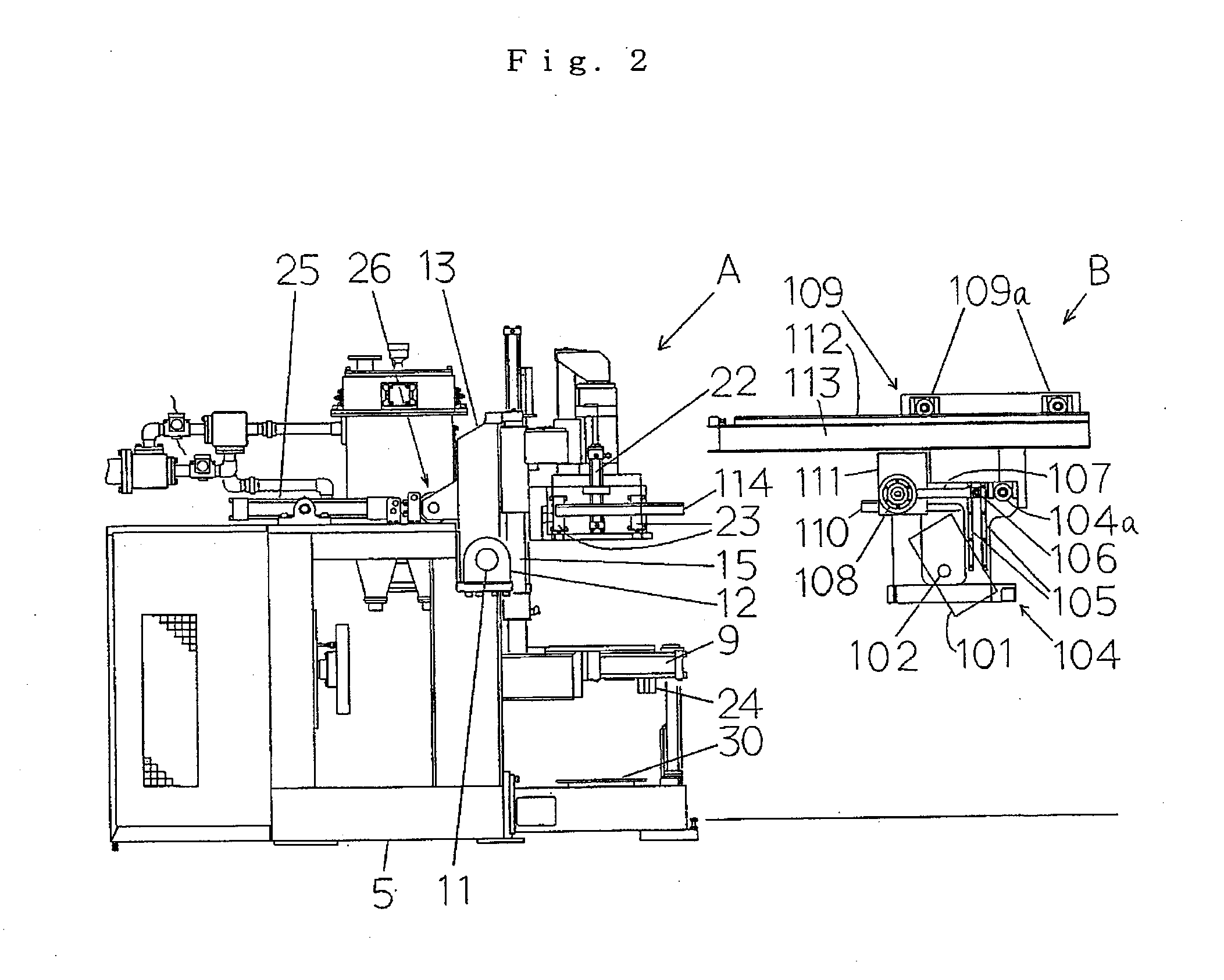
[0102]The portion contacting the core of the handling tool 201 is made from resin, and is designed so that it can be changed (not shown). Further, the handling tool 201 is provided with a holding means (not shown) to hold the core. In the second embodiment, a vacuuming means is used for holding the core and acts as the holding means. The holding means is not limited to the vacuuming means. For example, a clamping means to mechanically clamp the core can also be used for the holding means.

[0103]The carrier 204 for transferring the handling tool is provided with four rollers 204a, 204a disposed at the upper portion of its inside (see FIG. 14; two rollers of the front side of the carrier are depicted). A pair of guide members 205, 205 (see FIG. 12) is fixed to the front side of the carrier 204 at a predetermined interval. A roller 206 is slidably disposed between the pair of the guide members 205, 205. Further, the roller 206 is disposed at an arm 207. The arm 207 is connected to a rot...

first embodiment

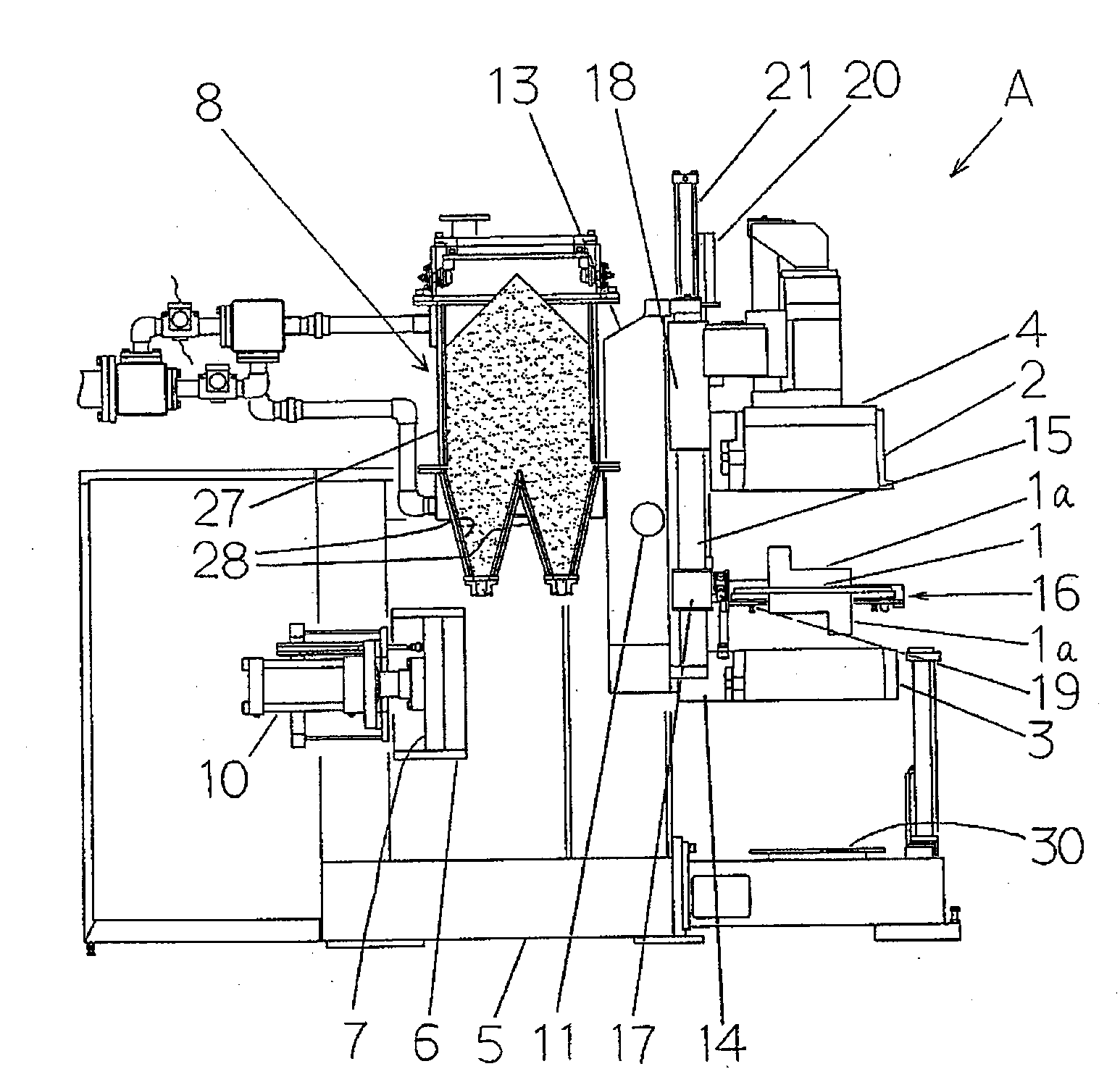
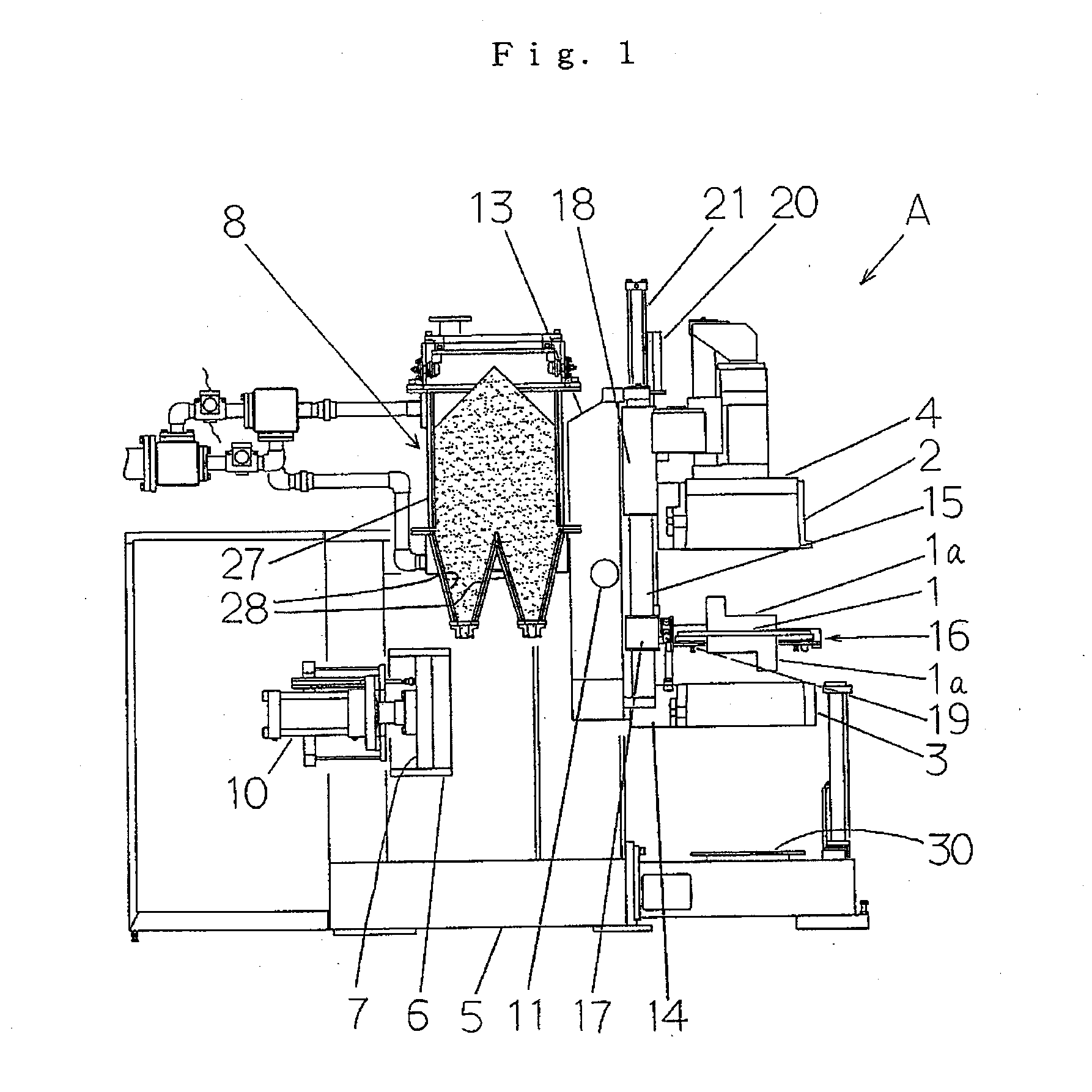
[0109]Below, the operations of the apparatus having the constitution explained in the above paragraphs are explained. After an upper and lower mold are molded in the flasks, the cope flask 2 and the drag flask 3 and the match plate 1 are separated. Then the match plate 1 is removed from the position between the cope flask 2 and the drag flask 3, as shown in FIG. 12. Since the operations of the apparatus up to the status shown in FIG. 12 are the same as those of the first embodiment, the explanation for the operations is omitted.

[0110]From the status shown in FIG. 12, the operations for setting a core in a mold are started. These operations are now explained in detail. FIG. 12 shows the state in which the carriage 209 is fixed to the position of the station S1 by means of the locking means (not shown) disposed at the station S1. In this state, the handling tool 201 is at an initial state, namely, it is inclined at a predetermined angle (in this embodiment, the angle is 30 degrees) by...


PUM


Abstract

These inventions provide a core-setting apparatus and a method for setting the core in a lower mold used for a molding apparatus, wherein the core-setting apparatus has a simple structure and can maintain the core in the mold in a highly accurate position. The inventions consist of:
    • the core-setting apparatus to set a core in the lower mold while the upper and the lower mold and a match plate are separated from each other after molding the upper and lower mold that comprises:
    • a handling tool having a holding means and a rotatable rod, wherein the handling tool is rotatably supported by the rod,
    • a carrier for transferring the handling tool, wherein the carrier supports the rotatable rod and is moved to or from the location above the lower mold, and
    • an actuator for lowering and lifting the cope flask together with the carrier and the handling tool which are located above the drag flask, wherein the actuator is mounted on the main body of the molding apparatus.

Description

TECHNICAL FIELD[0001]These inventions relate to a core-setting apparatus used for a flaskless molding apparatus for producing a pair of an upper and a lower mold, which molding apparatus uses a match plate, and a method for setting a core.BACKGROUND OF THE INVENTIONS[0002]Conventionally, as one core-setting apparatus that is used for a flaskless molding apparatus for producing a pair of an upper and a lower mold by using a match plate, there is a type of apparatus that comprises the following:[0003]after a drag flask is placed outside the apparatus by moving it forward from the apparatus, wherein the drag flask is movable forward and backward,[0004]a core-setting apparatus sets a core in a lower mold in the drag flask, wherein the core-setting apparatus is disposed above the drag flask. (See Patent Document 1.)[0005]Patent Document 1: Pamphlet of International Patent Laid-open Publication No. WO 02 / 43901 (See FIG. 3.)DISCLOSURES OF INVENTIONS[0006]However, for the inventions of Pate...

Claims


Application Information

Patent Timeline
IPC IPC(8): B29C39/00B29C33/00
CPCB22C9/108B22C15/08B22C15/02B22C11/10
Inventor HIRATA, MINORUSAKAGUCHI, KOICHI
Owner SINTOKOGYI LTD
Why Eureka
Try Eureka