Check patentability & draft patents in minutes with Patsnap Eureka AI!

Motion control device for vehicle

a technology of motion control and vehicle, which is applied in the direction of brake systems, instruments, tractors, etc., can solve the problems of low sense of low sense of the security of the driver, and less driver comfor

Active Publication Date: 2009-08-06
ADVICS CO LTD +1
View PDF14 Cites 22 Cited by
  • Summary
  • Abstract
  • Description
  • Claims
  • Application Information

AI Technical Summary

Benefits of technology

[0008]According to an aspect of the present invention, a motion control device for a vehicle includes a vehicle speed obtaining device for obtaining a speed of the vehicle, a curvature obtaining device for obtaining a bending grade of a curve existing ahead of the vehicle on a road on which the vehicle travels, a position obtaining device for obtaining a relative position of the vehicle relative to the curve, a determination device for determining an appropriate vehicle speed for the vehicle passing through the curve on the basis of the bending grade of the curve, a speed reduction control device for executing a speed reduction control for reducing the speed of the vehicle on the basis of the speed of the vehicle and the relative position so that the vehicle passes through the curve at the appropriate vehicle speed, and a gradient obtaining device for obtaining a gradient of the road on the curve on the road in a traveling direction of the vehicle, wherein the determination device determines the appropriate vehicle speed on the basis of the gradient of the road in addition to the bending grade of the curve.
[0009]According to another aspect of the present invention, a motion control device for a vehicle includes a vehicle speed obtaining device for obtaining a speed of the vehicle, a curvature obtaining device for obtaining a bending grade of a curve existing ahead of the vehicle on a road on which the vehicle travels, a position obtaining device for obtaining a relative position of the vehicle relative to the curve, a determination device for determining an appropriate vehicle speed for the vehicle passing through the curve on the basis of the bending grade of the curve, a speed reduction control device for executing a speed reduction control for reducing the speed of the vehicle on the basis of the speed of the vehicle and the relative position so that the vehicle passes through the curve at the appropriate vehicle speed, and an index obtaining device for obtaining an index that indicates a degree of poor visibility of the curve to the driver, wherein the determination device determines the appropriate vehicle speed on the basis of the index in addition to the bending grade of the curve.
[0010]According to a further aspect of the present invention, a motion control device for a vehicle includes a vehicle speed obtaining device for obtaining a speed of the vehicle, a curvature obtaining device for obtaining a bending grade of a curve existing ahead of the vehicle on a road on which the vehicle travels, a position obtaining device for obtaining a relative position of the vehicle relative to the curve, a calculation device for calculating an allowable lateral acceleration, which is an allowable value of a lateral acceleration acting on the vehicle when passing through the curve, a determination device for determining an appropriate vehicle speed for the vehicle passing through the curve on the basis of the bending grade of the curve and the

Problems solved by technology

Hence, the driver may feel less secure (i.e. the sense of security of the driver is low).
Further, in a case where visibility of the curve is poor because relief of the curve is great, because an elevation of an inner side of the curve is higher than the elevation of the curve, or because of an existence of a tall building at the inner side of the curve, the sense of the security of the driver may be low.
On the other hand, the driver may feel less secure when the vehicle travels the curve having a great curvature radius of the curve at a high speed even if the vehicle travels through the curve while receiving the predetermined same level of the lateral acceleration.

Method used


Image

  • Motion control device for vehicle
  • Motion control device for vehicle
  • Motion control device for vehicle

Examples


Embodiment Construction

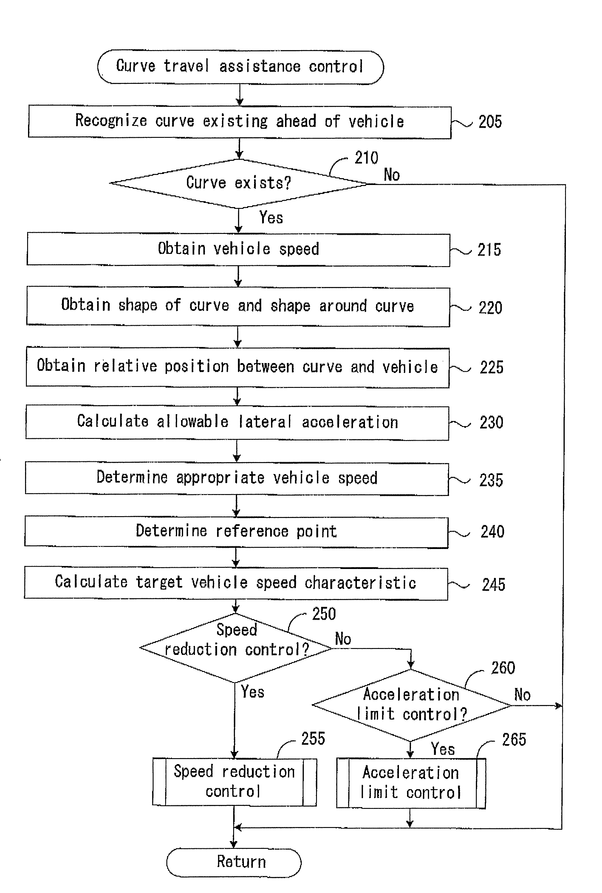
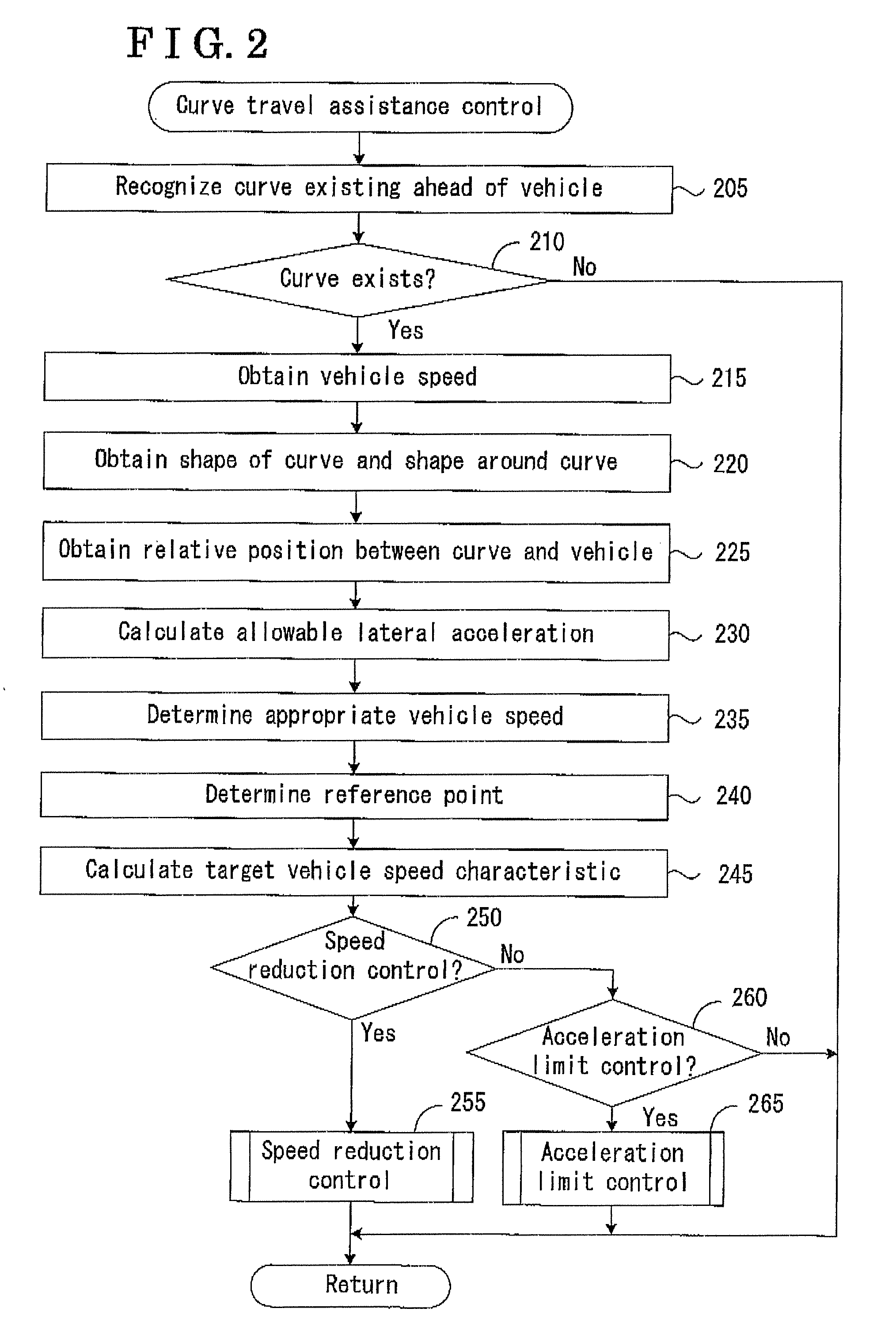
[0031]An embodiment of a motion control device (a speed reduction control device) for a vehicle will be described below in accordance with the attached drawings.

[0032][Configuration]

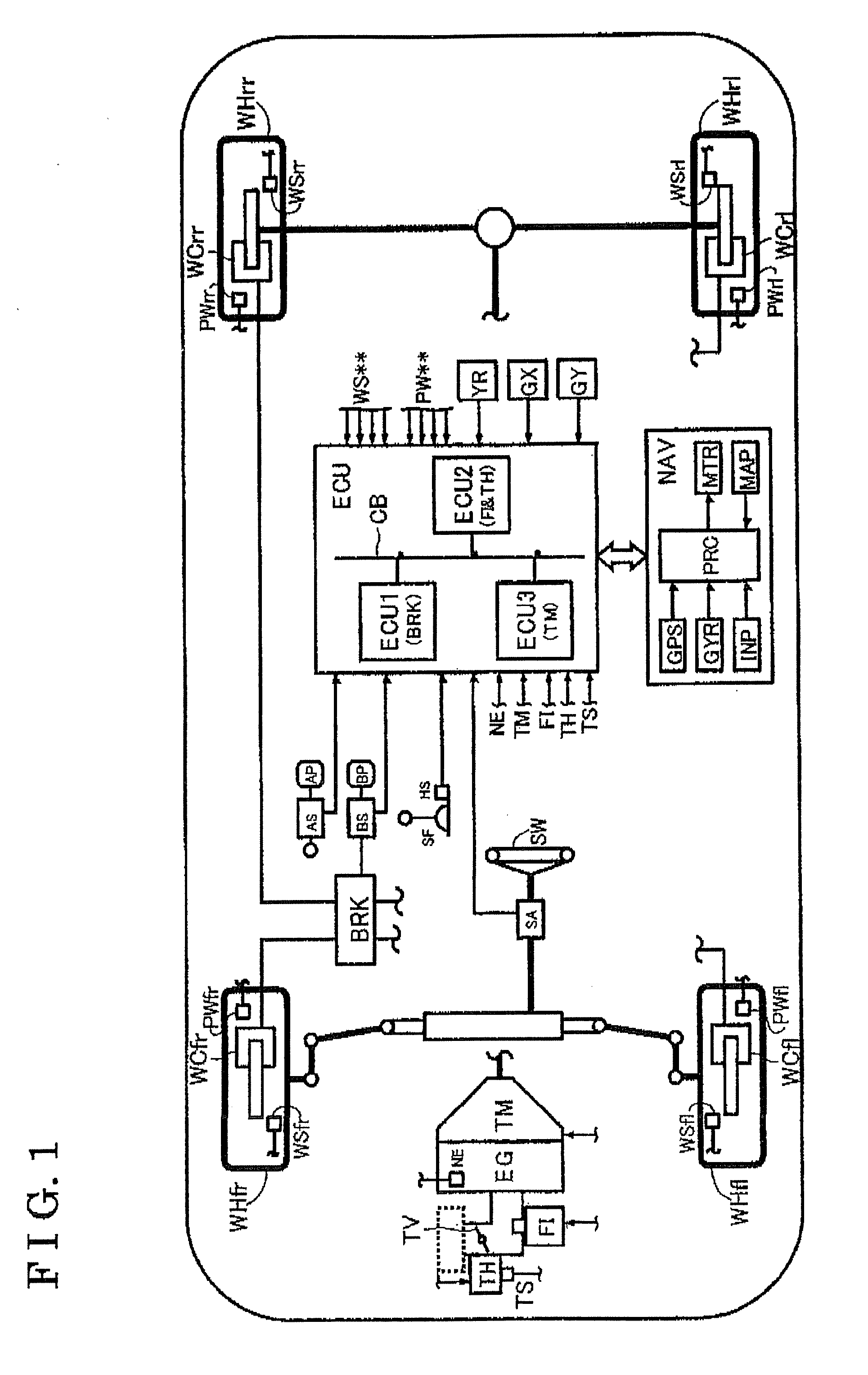
[0033]FIG. 1 schematically illustrates a structure of the vehicle to which the motion control device (which is hereinafter referred to as a devise) is provided. The device includes an engine EG, which serves as a power source, an automatic transmission TM, a brake actuator BRK, an electronic control unit ECU and a navigation device NAV.

[0034]For example, an internal combustion engine is used as the engine EG. More specifically, an opening degree of a throttle valve TV is adjusted by a throttle actuator TH in response to an operation of an acceleration pedal (acceleration operation member) AP by a driver. An amount of fuel proportional to an inhaled air volume, which is adjusted in response to the opening degree of the throttle valve TV, is injected by a fuel injection actuator FI (an injector). As a resu...


PUM


Abstract

A motion control device for a vehicle includes a vehicle speed obtaining device, a curvature obtaining device for obtaining a bending grade of a curve existing ahead of the vehicle, a position obtaining device for obtaining a relative position between the vehicle and the curve, a determination device for determining an appropriate vehicle speed for the vehicle passing through the curve based on the bending grade, a speed reduction control device for executing a speed reduction control for reducing the vehicle speed based on the vehicle speed and the relative position so that the vehicle passes through the curve at the appropriate vehicle speed, and a gradient obtaining device for obtain a gradient of the road on the curve existing in a traveling direction of the vehicle, wherein the determination device determines the appropriate vehicle speed based on the gradient of the road in addition to the bending grade.

Description

CROSS REFERENCE TO RELATED APPLICATIONS[0001]This application is based on and claims priority under 35 U.S.C. §119 to Japanese Patent Application 2008-021627, filed on Jan. 31, 2008, the entire contents of which is incorporated herein by reference,FIELD OF THE INVENTION[0002]The present invention relates to a motion control device for a vehicle. More specifically, the present invention pertains to a motion control device for a vehicle for executing an automatic reduction of a speed of the vehicle (i.e. a speed reduction control) while the vehicle travels through a curve existing ahead of the vehicle on a road on which the vehicle is traveling.BACKGROUND[0003]Disclosed in JP2004-230946A is an example of a motion control device for a vehicle. In the motion control device for the vehicle disclosed in JP2004-230946A, an allowable value of a lateral acceleration (i.e. allowable lateral acceleration), which acts on the vehicle when the vehicle travels through a curve, is determined on the...

Claims


Application Information

Patent Timeline
IPC IPC(8): G06F7/00B60T7/12B60W10/04B60W10/06B60W10/10B60W10/18B60W10/188B60W30/00B60W40/072B60W40/076B60W40/10B60W40/109G08G1/16
CPCB60T2201/16B60T2210/22B60T2210/24B60W10/02B60W10/06B60W10/11B60W10/184B60W2520/125B60W2720/103B60W2552/20B60W2556/50B60W2552/30B60W50/0097B60W30/18145
Inventor YASUI, YOSHIYUKINAKANO, KEITAKUKI, YOSUKEMIYAJIMA, TAKAYUKIKONDO, YOSHITOTAKEUCHI, ATSUSHI
Owner ADVICS CO LTD
Features
  • R&D
  • Intellectual Property
  • Life Sciences
  • Materials
  • Tech Scout
  • Unparalleled Data Quality
  • Higher Quality Content
  • 60% Fewer Hallucinations
Learn More