Antenna arrangement for a portable radio coummunication device, and a portable radio communication device comprising such an antenna arrangement
- Summary
- Abstract
- Description
- Claims
- Application Information
AI Technical Summary
Benefits of technology
Problems solved by technology
Method used
Image

Examples
Example
[0027]A first embodiment of the present invention will now be described with reference to FIGS. 6-9.
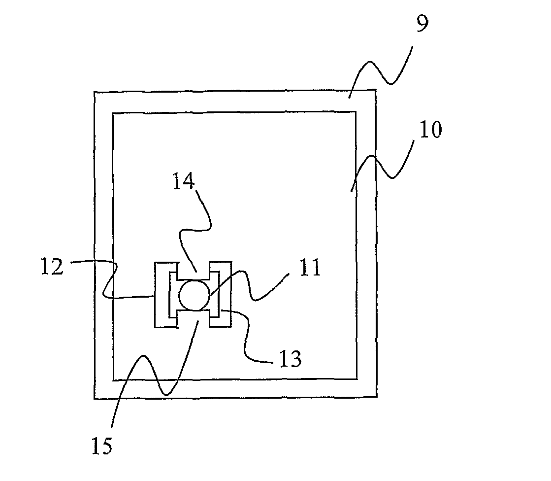
[0028]An antenna arrangement for a portable radio communication device, such as e.g. a mobile phone, a PDA or a portable computer, comprises a substantially planar flexible antenna element 10, such as a flex film antenna element, and a support structure 9 for support of the antenna element 10. The flexible antenna element 10 includes two connection portions 14 and 15, e.g. for feeding the antenna or for grounding the antenna. The connection portions 14, 15 are preferably provided by punching out part 12 of the flexible antenna element 10, resulting in two connection portions 14, distanced from the rest of the antenna element 10. Alternatively the connection portions 14, 15 can be provided by cutting a pattern in the flexible antenna element 10.
[0029]The support structure 9 includes an aperture 13 for receiving an outer end of the connection portions 14 and 15. The antenna arrangement ...
Example
[0039]A second embodiment of the present invention will now be described with reference to FIGS. 11-13. This second embodiment of the present invention is identical to the first embodiment described above, apart from the following.
[0040]The aperture 16 has a cross-section of two arc-shaped portions with two planar portions 17 there between. The planar portions 17 are for receiving parts of the connection portions 19 and 20. Thus, a rounded surface of the connection device (not shown to not clutter the figure) presses against the connection portions 19 and 20, which are supported by a planar surface. Also, a rounded surface of the connection device (not shown) presses against a correspondingly rounded surface of the circular part of the aperture 16. Preferably, the punch-out 18 of the substantially planar flexible antenna element antenna element is also substantially circular, which provides for further reduction in frequency deviations.
Example
[0041]A third embodiment of the present invention will now be described with reference to FIG. 14. This third embodiment of the present invention is identical to the second embodiment described above, apart from the following.
[0042]The antenna element 10 is shaped with four connection portions 22, 23, 24 and 25, for mounting in the aperture 21 having four planar portions between arc-shaped portions. The punch-out 26 of the antenna element 10 is further essentially circular.
[0043]Alternatively the antenna element can be shaped with three or five or more connection portions. Further, the connection portions of the above embodiments have been illustrated as symmetrically distributed around the connection device, which they preferably also are.
[0044]A connection device described in the embodiments above may e.g. be used for grounding when the antenna element is a parasitic element, or for feeding when no grounding point is necessary, such as for a folded monopole. Further, two or more c...
PUM
 Abstract
Description
Claims
Application Information
 - R&D Engineer
- R&D Manager
- IP Professional
- Industry Leading Data Capabilities
- Powerful AI technology
- Patent DNA Extraction
Browse by: Latest US Patents, China's latest patents, Technical Efficacy Thesaurus, Application Domain, Technology Topic.
© 2024 PatSnap. All rights reserved.Legal|Privacy policy|Modern Slavery Act Transparency Statement|Sitemap