Fire gas detector-coding

Active Publication Date: 2010-02-04
JOHNSON CONTROLS FIRE PROTECTION LP +1
View PDF5 Cites 0 Cited by
  • Summary
  • Abstract
  • Description
  • Claims
  • Application Information

AI Technical Summary

Benefits of technology

[0006]An aim of the invention is to provide a fire detect

Problems solved by technology

The problem with known fire detectors is that each type of sensing element tends to decay with time, without there being provided means for accurately establishing exactly how much the sensitivity of its sensing element has changed since installation.
This problem is exacerbated where a fire detector is provided with t

Method used


Image

  • Fire gas detector-coding
  • Fire gas detector-coding

Examples


Example

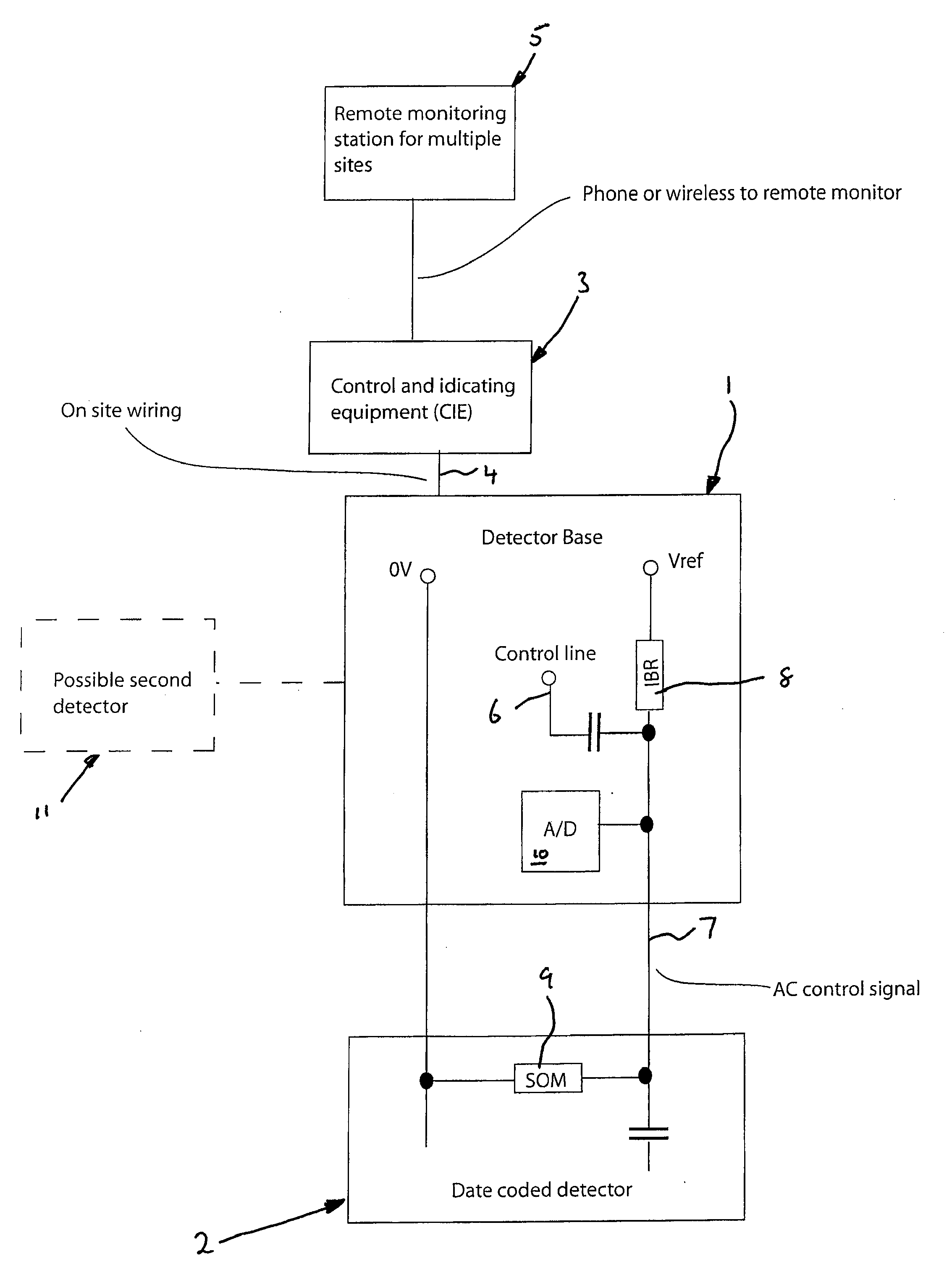
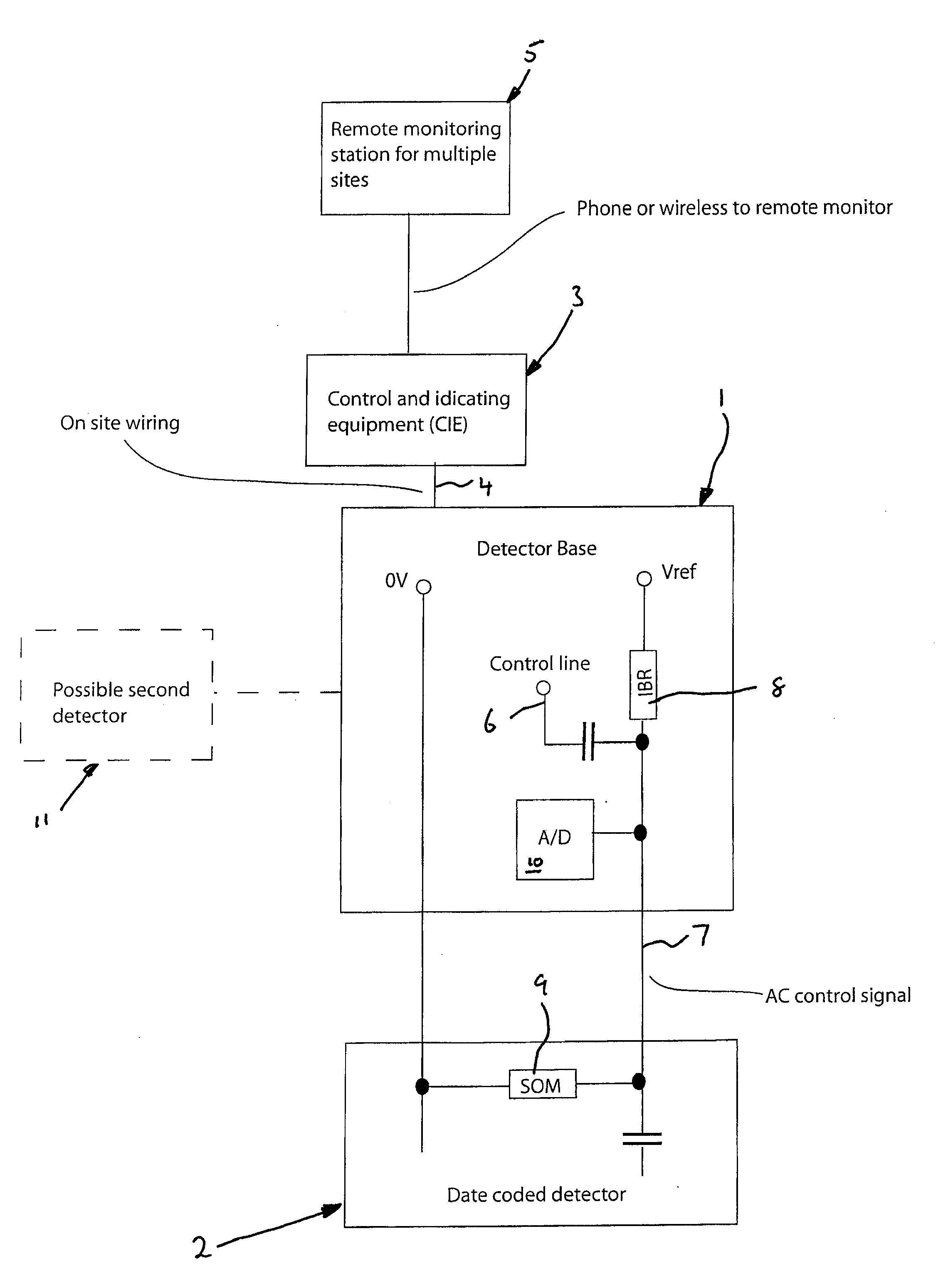
[0023]The disclosure can be better understood with reference to the following drawing and description. The components in the FIGURE are not necessarily to scale, emphasis instead being placed upon illustrating the principles of the present disclosure. Moreover, in the FIGURE, like referenced numerals designate corresponding parts or elements throughout the different views.

[0024]Referring to the drawing, a fire detector is constituted by a detector base 1 and a sensor 2. The detector base is attached to a software-controlled CIE 3 by on-site wiring 4. The CIE 3 is connectable wirelessly to a remote monitoring station 5. The CIE 3 is associated with a plurality of other fire detectors (not shown), thereby constituting a central control for all the fire detectors.

[0025]The detector base 1 is provided with a control line 6 which is used to send a signal, via an AC control line 7, to the sensor 2 for carrying out a self-test of that sensor.

[0026]The detector base 1 is provided with an in...


PUM


Abstract

A detector comprises a detector base and a sensor, first and second resistors connected in series, a DC voltage source (Vref) connected to the resistors, and means for monitoring the voltage at the midpoint of a potential divider constituted by the series-connected resistors. The first and second resistors are rated so that the midpoint voltage is indicative of the date of manufacture of the sensor.

Description

CROSS-REFERENCE TO RELATED APPLICATIONS[0001]This application claims priority to PCT Application No. PCT / GB2008 / 000876 filed on Mar. 13, 2008 (published as WO 2008 / 117016 A1), titled “Detector”; which claims priority to United Kingdom Application No. 0705888.6 filed on Mar. 27, 2007 (published as GB 2 447 917 A), titled “Detector”; and is a continuation-in-part of U.S. application Ser. No. 11 / 587,461 filed on Oct. 25, 2006 (published as U.S. Patent Application No. 2007 / 0216527), titled “Testing a Fire Detector Sensor”; which is a national phase application of PCT Application No. PCT / GB2005 / 001641 filed on Apr. 29, 2005 (published as WO 2005 / 106822 A1), titled “Testing a Fire Detector Sensor”; which claims priority to United Kingdom Application No. 0409759.8 filed on Apr. 30, 2004 (published as GB 2 413 635 A), titled “Testing a Fire Detector Sensor”. U.S. application Ser. No. 11 / 587,461 (published as U.S. Patent Application No. 2007 / 0216527), PCT Application No. PCT / GB2005 / 001641 (p...

Claims


Application Information

Patent Timeline
IPC IPC(8): G08B17/10G08B21/00G08B29/00
CPCG08B21/14G08B29/183G08B29/145G08B29/043
Inventor BENNETT, STEVEN IANBRIGHENTI, DONPICCOLO, JOEBABINEAU, KIMBERLY
Owner JOHNSON CONTROLS FIRE PROTECTION LP
Why Eureka
Try Eureka