Heater and method for manufacturing the same
- Summary
- Abstract
- Description
- Claims
- Application Information
AI Technical Summary
Benefits of technology
Problems solved by technology
Method used
Image

Examples
Example
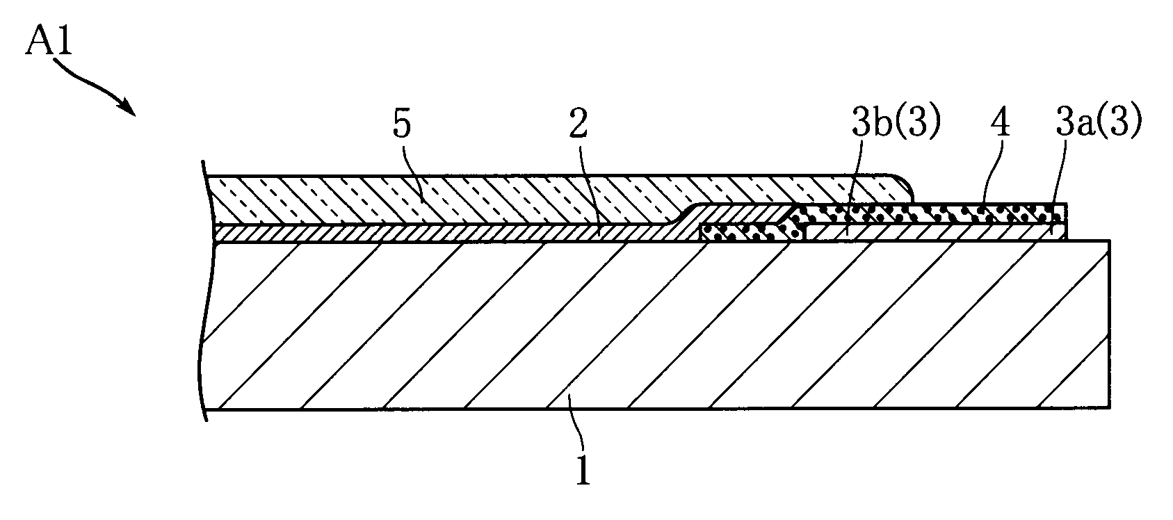
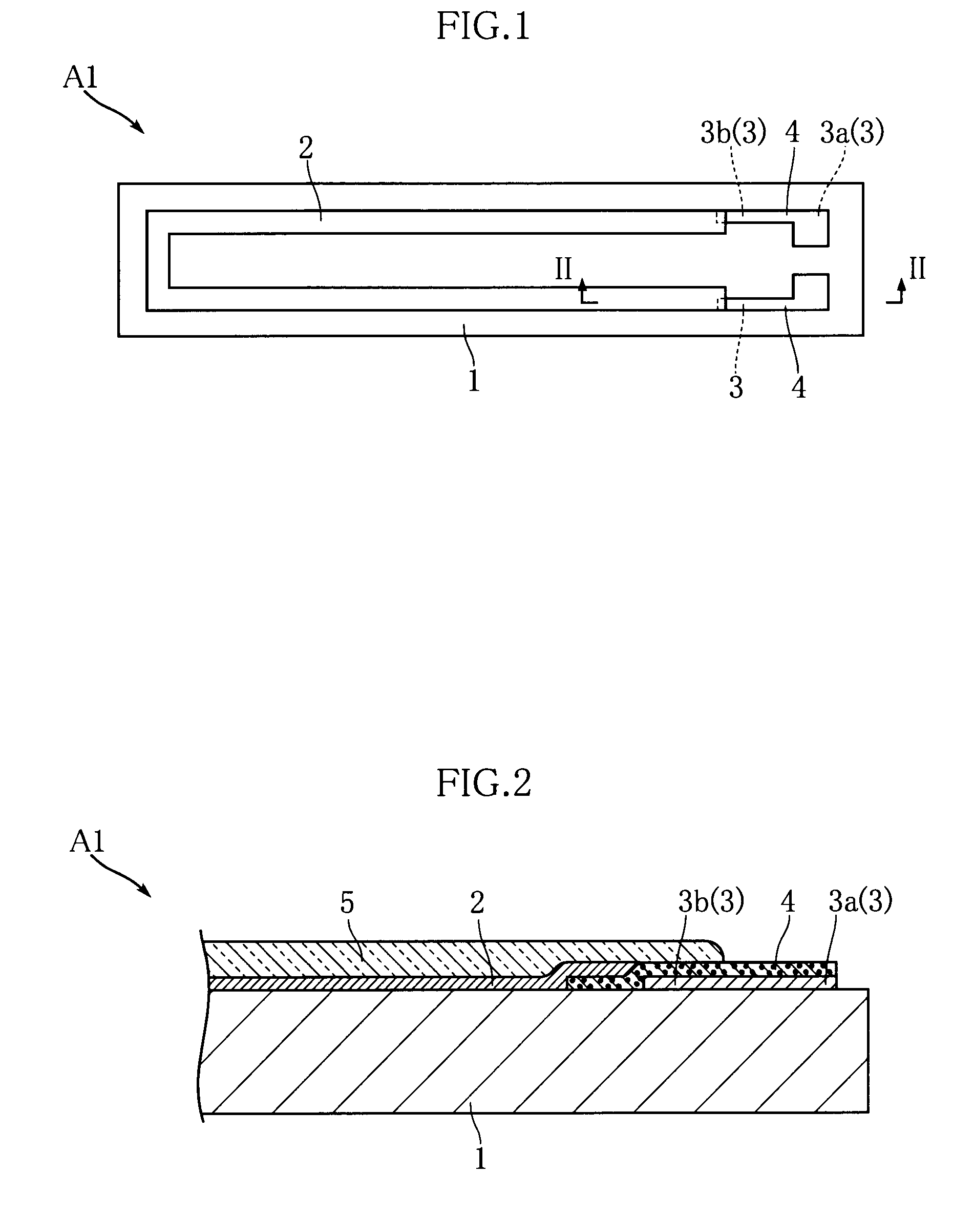
[0026]FIGS. 1 and 2 show a heater according to a first embodiment of the present invention. The heater A1 of this embodiment includes a substrate 1, a heating resistor 2, an electrode 3, a diffusion prevention layer 4 and a protective film 5. The heater A1 is used in e.g. a laser printer to thermally fix toner transferred to recording paper. For easier understanding, the illustration of the protective film 5 is omitted in FIG. 1.
[0027]The substrate 1 is in the form of an elongated rectangle and made of an insulating material. Examples of the insulating material include AlN and Al2O3.
[0028]The heating resistor 2 is provided on the substrate 1 and in the form of a generally U-shaped strip. The heating resistor 2 includes, as a resistive material, Ag—Pd. The proportion of Pd in Ag—Pd is e.g. 50 to 60 wt %. The particle size of Ag contained in the heating resistor 2 is about 1.0 to 3.0 μm. The heating resistor 2 further includes crystallized glass such as SiO2—B2O3—R-based glass or SiO2...
Example
[0043]FIG. 5 shows a heater according to a second embodiment of the present invention. The heater A2 of this embodiment differs from that of the foregoing embodiment in position of the end of the heating resistor 2. In this embodiment, the heating resistor 2 overlaps part of the electrode 3 by extending beyond the portion of the diffusion prevention layer 4 which projects from the electrode 3.
[0044]In this embodiment again, the separation of the heating resistor 2 and the electrode 3 is prevented. The diffusion prevention layer 4 overlaps at least one of the heating resistor 2 and the electrode 3. Thus, the current applied to the heater A2 flows to both of the diffusion prevention layer 4 and the heating resistor 2 or both of the diffusion prevention layer 4 and the electrode 3. This prevents excessive heat generation at part of the diffusion prevention layer 4.
Example
[0045]FIG. 6 shows a heater according to a third embodiment of the present invention. The heater A3 of this embodiment differs from any of the foregoing embodiments in shape of the diffusion prevention layer 4. Specifically, in this embodiment, the diffusion prevention layer 4 is made up of an intervening portion 4b and a pad portion 4a. The intervening portion 4b is disposed between the heating resistor 2 and the electrode 3. The pad portion 4a is exposed out of the protective film 5 and may be rectangular in plan view. In this embodiment again, the separation of the heating resistor 2 and the electrode 3 is prevented. The pad portion 4b is suitably utilized as a part to be clipped by a power supply clip for supplying power to the heater A3.
PUM
| Property | Measurement | Unit |
|---|---|---|
| Softening point | aaaaa | aaaaa |
Abstract
Description
Claims
Application Information
 - R&D Engineer
- R&D Manager
- IP Professional
- Industry Leading Data Capabilities
- Powerful AI technology
- Patent DNA Extraction
Browse by: Latest US Patents, China's latest patents, Technical Efficacy Thesaurus, Application Domain, Technology Topic.
© 2024 PatSnap. All rights reserved.Legal|Privacy policy|Modern Slavery Act Transparency Statement|Sitemap