Check patentability & draft patents in minutes with Patsnap Eureka AI!

Construction Frame Shear Lug

a construction frame and shear lug technology, applied in the field of shear lugs, can solve the problems of reducing the ability of the foundation to absorb the applied shear force, so as to achieve the effect of discharging the shear force to the foundation

Active Publication Date: 2010-05-06
SIMPSON STRONG TIE
View PDF8 Cites 17 Cited by
  • Summary
  • Abstract
  • Description
  • Claims
  • Application Information

AI Technical Summary

Benefits of technology

[0008]Embodiments of the present invention relate to a shear lug for transferring shear stresses from a structural element, such as a column in a framing element, down into the foundation supporting the framing element. The shear lug is not initially affixed to the structural element. The shear lug is instead affixed to anchor rods of an anchorage assembly, and is installed into the foundation with the anchorage assembly at the time the concrete foundation is poured. The structural element is subsequently affixed to the anchor rods, so that shear forces are transferred from the structural element, through the anchor rods and to the shear lugs, which effectively dissipate the shear forces to the foundation.
[0009]A shear lug according to embodiments of the present invention is more effective at distributing shear loads from structural elements to the foundation than conventional shear lugs. In particular, as the present shear lug is mounted within the foundation when the foundation is poured, and subsequently attached to the structural element, the likelihood that the shear lug will fracture the foundation is reduced. Moreover, as the present shear lug is formed of a unitary angled piece of steel, as opposed to a fin welded onto a base plate, the problem of weld failure is alleviated.

Problems solved by technology

For example, fitting the shear lug to a preformed key in the foundation weakens the foundation and reduces the ability of the foundation to absorb the applied shear forces.
Additionally, the weld of the shear lug to the base plate is subject to high stresses and can at times fail under high shear loads.

Method used


Image

  • Construction Frame Shear Lug
  • Construction Frame Shear Lug
  • Construction Frame Shear Lug

Examples


Embodiment Construction

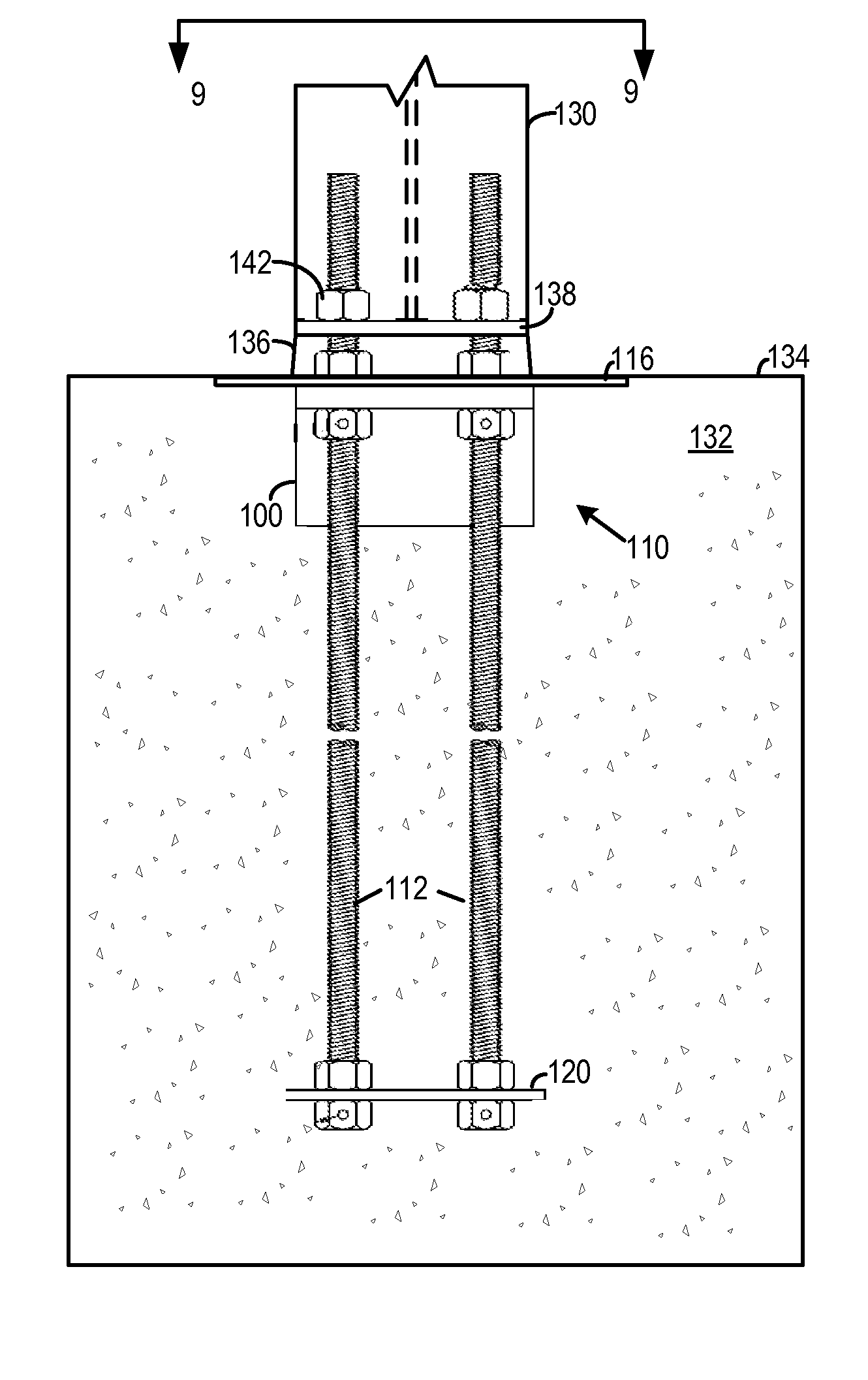
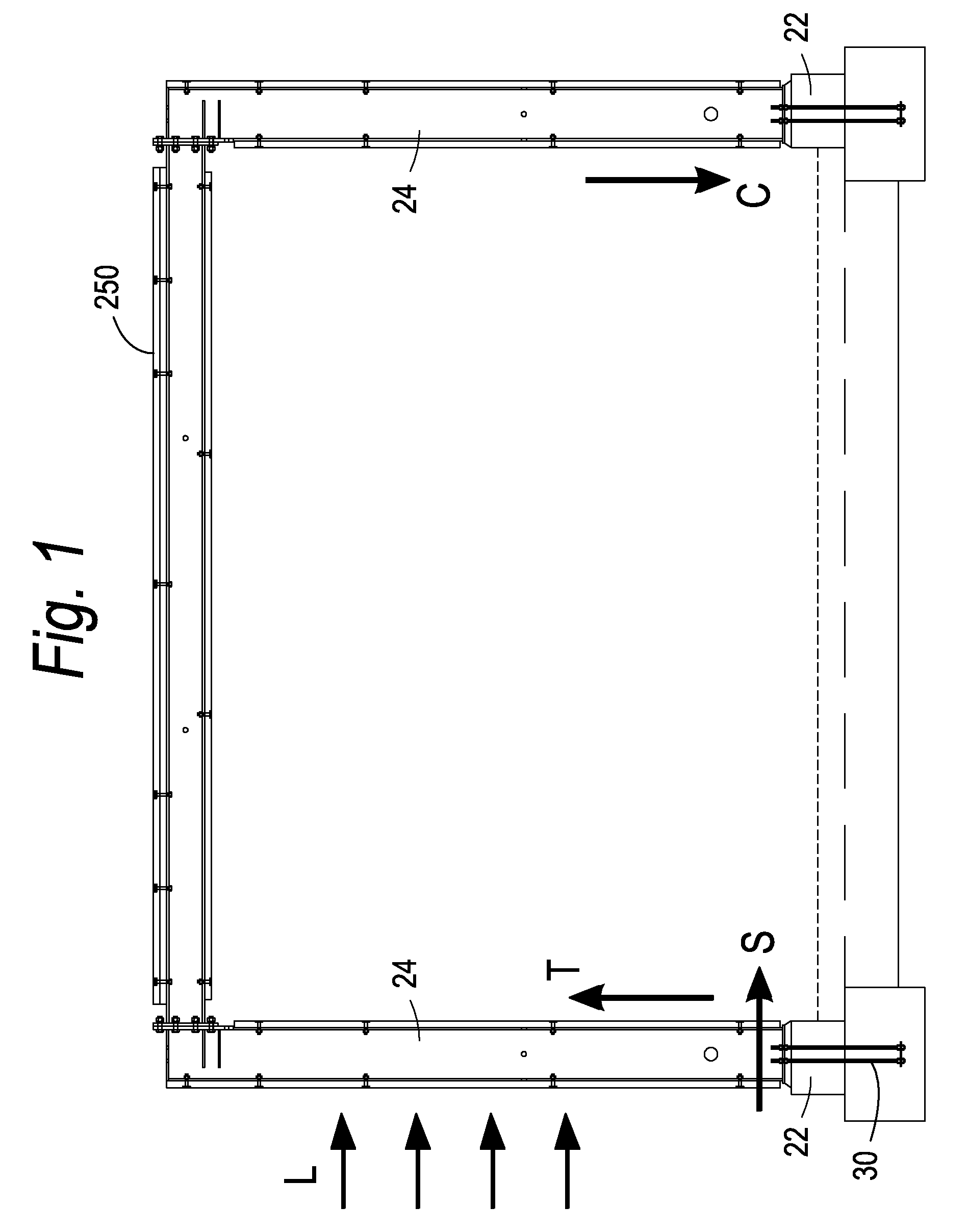
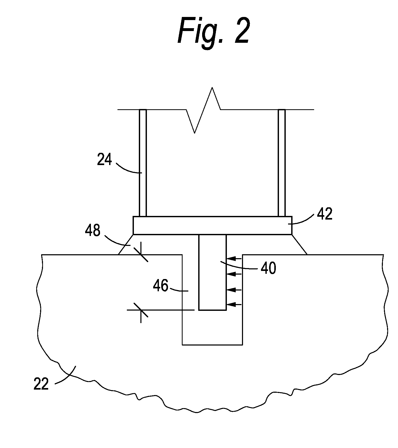
[0023]The present invention will now be described with reference to FIGS. 3 through 21, which in embodiments relate to a shear lug for transferring shear loads from framing members to a foundation on which the framing member is supported. It is understood that the present invention may be embodied in many different forms and should not be construed as being limited to the embodiments set forth herein; rather these embodiments are provided so that this disclosure will be thorough and complete and will fully convey the invention to those skilled in the art. Indeed, the invention is intended to cover alternatives, modifications and equivalents of these embodiments, which are included within the scope and spirit of the invention as defined by the appended claims. Furthermore, in the following detailed description of the present invention, numerous specific details are set forth in order to provide a thorough understanding of the present invention. However, it will be clear to those of o...


PUM


Abstract

A shear lug is disclosed for transferring shear stresses from a structural element, such as a column in a framing element, down into the foundation supporting the framing element. The shear lug is not initially affixed to the structural element. The shear lug is instead affixed to anchor rods of an anchorage assembly, and is installed into the foundation with the anchorage assembly at the time the concrete foundation is poured. The structural element is subsequently affixed to the anchor rods, so that shear forces are transferred from the structural element, through the anchor rods and to the shear lugs, which effectively dissipate the shear forces to the foundation.

Description

BACKGROUND OF THE INVENTION[0001]1. Field of the Invention[0002]The present invention relates to load bearing in the construction of buildings and in particular to a shear lug for transmitting shear forces from framing elements to a foundation on which the framing elements are supported.[0003]2. Description of the Related Art[0004]Framing elements used for example in lightweight constructions are mounted to foundations so as to resist a variety of forces. An example of a framing element 20 is shown in prior art FIG. 1 mounted to a foundation 22. Lateral loads, L, may be exerted on the framing element 20, for example upon seismic activity or winds. The lateral loads L as shown generate tensile forces T and compressive loads C on respective columns 24 of the framing element 20 as shown. In order to transfer the tensile loads from the column 24 to the foundation 22, anchor rods 30 are bolted to the column base and extend through the base down into the concrete foundation.[0005]In addit...

Claims


Application Information

Patent Timeline
IPC IPC(8): E04B1/41
CPCE04B1/24E04B1/4157E04B2001/2496E04B2001/2463E04B2001/2487E04B2001/2448
Inventor MONTAGUE, EMORY L.MCENTEE, PAUL
Owner SIMPSON STRONG TIE
Features
  • R&D
  • Intellectual Property
  • Life Sciences
  • Materials
  • Tech Scout
  • Unparalleled Data Quality
  • Higher Quality Content
  • 60% Fewer Hallucinations
Learn More