Wireless relay apparatus and wireless relay method
Active Publication Date: 2010-08-05
PANASONIC CORP
View PDF9 Cites 24 Cited by
Summary
Abstract
Description
Claims
Application Information
AI Technical Summary
This helps you quickly interpret patents by identifying the three key elements:
Problems solved by technology
Method used
Benefits of technology
Benefits of technology
[0045]The wireless relay apparatus according to the present invention enables low-delay and high-quality tr
Problems solved by technology
However, the buffer overflows when the reduction in the effective bandwidth exceeds the capacity of the buffer.
As a result, the packets to be transmitted are disposed, and if the data to be transmitted is video data, the video becomes blurry and the reproduction delays.
This is likely to cause buffer overflow in the wireless relay apparatuses due to the effect of the variations in the radio band, that is, the communication failure is likely to occur.
The communication failure refers to a failure in communication caused by errors in transmission and by congestion.
The communication failure assumes, for example, a case where the congestion occurs in the wireless relay apparatus due to the traffic interference as a result of converging traffic an
Method used
Image
Click on the blue label to locate the original text in one second.
Reading with bidirectional positioning of images and text.
Examples
embodiment 1
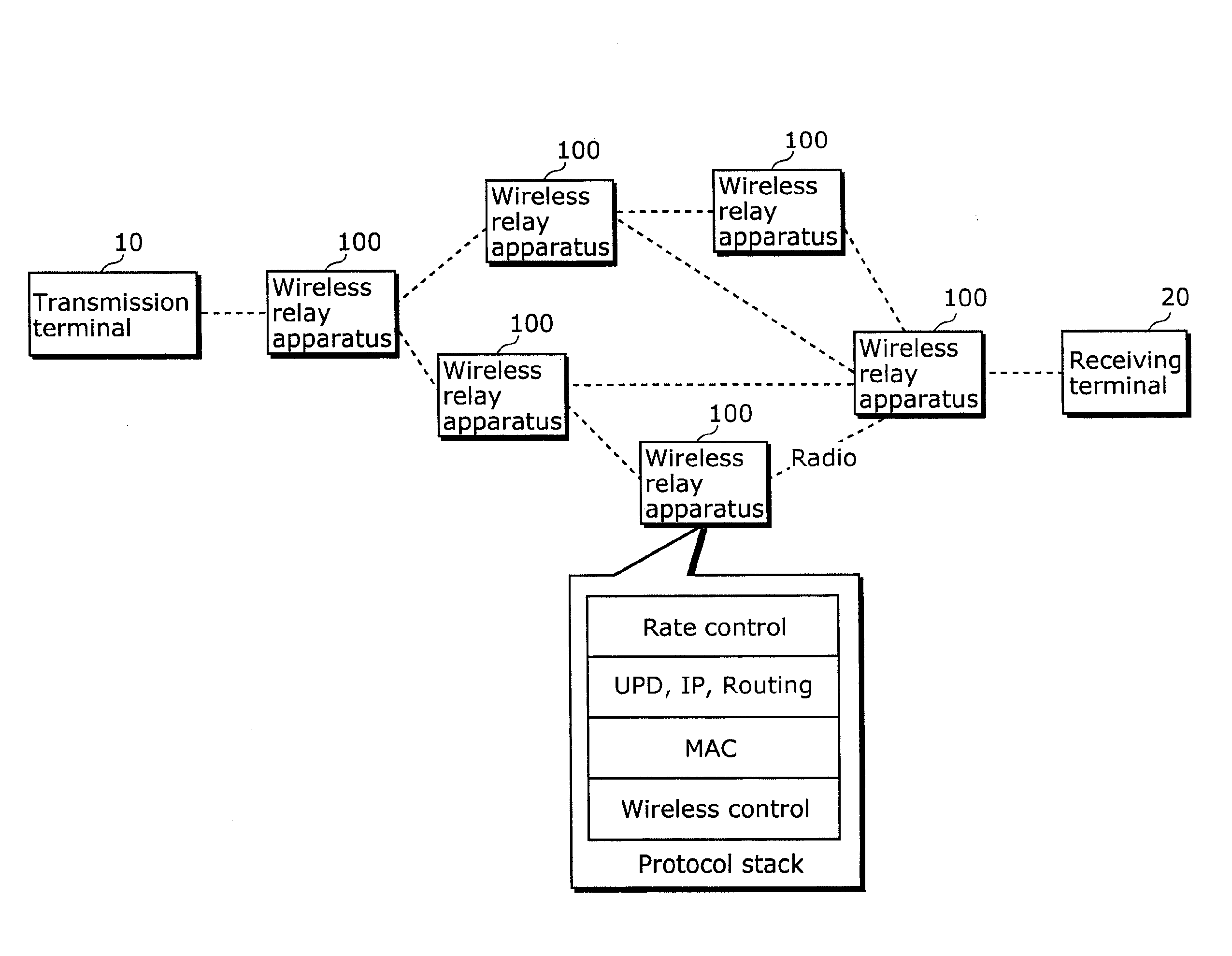
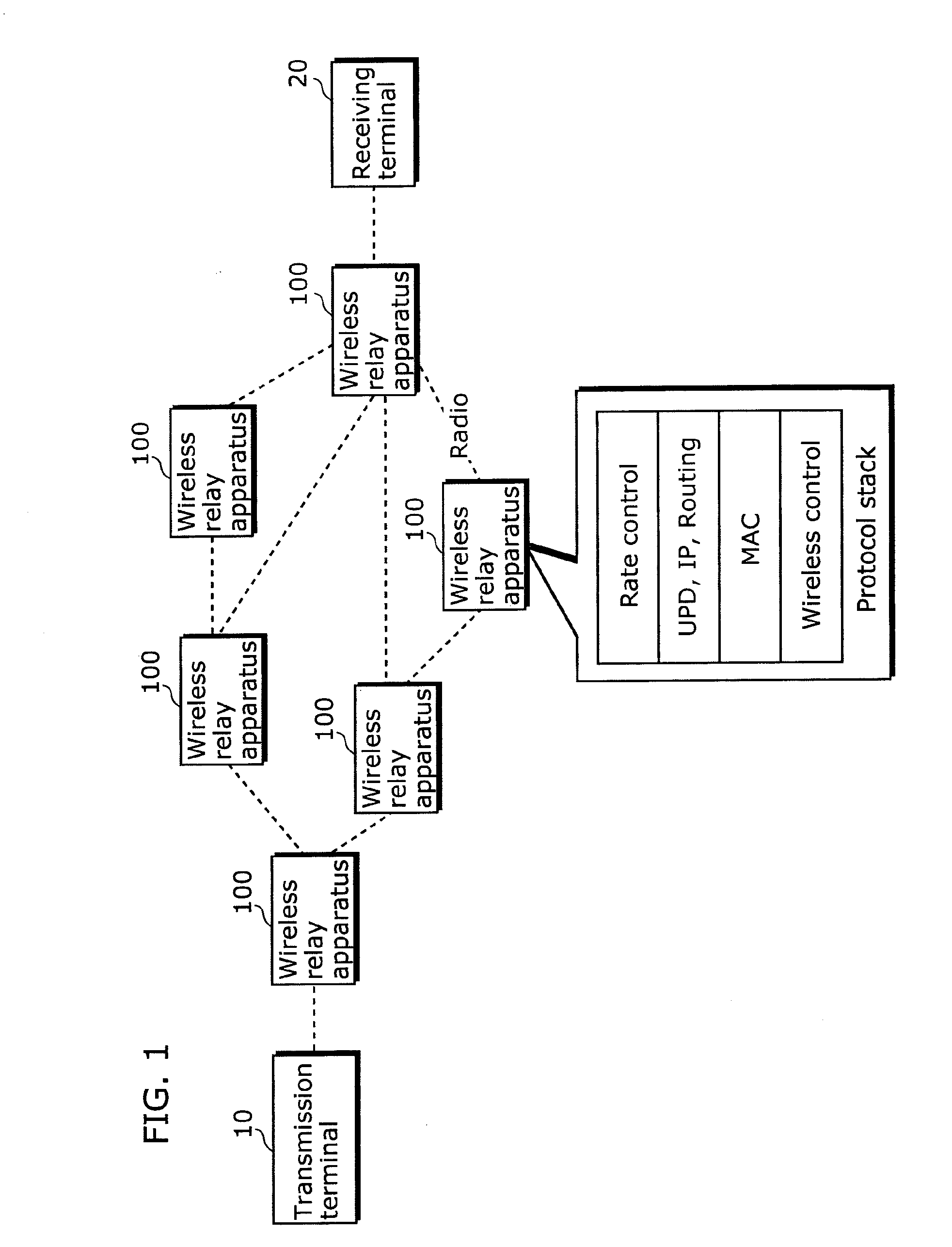
[0074]FIG. 1 is a diagram for describing a network configured including the wireless relay apparatuses according to Embodiment 1 of the present invention.
[0075]The network is configured, for example, as an ad-hoc network, and includes a transmission terminal 10, wireless relay apparatuses 100, and a receiving terminal 20.
[0076]The wireless relay apparatus 100 performs wireless relaying by protocol stack. The protocol stack includes a wireless control layer, a Media Access Control (MAC) layer, a transport layer related to the User Datagram Protocol (UDP), the Internet Protocol (IP) and routing, and a rate control layer.
[0077]The wireless control layer controls the allocation of the frequency, radio wave output (intensity), and directivity.
[0078]The MAC layer is included in the data link layer, and performs control using the access methods such as 802.11a, 802.11b, and Time Division Multiple Access (TDMA) method.
[0079]The rate control layer controls the amount of transmission at an ap...
embodiment 2
[0190]The wireless relay apparatus 100 according to Embodiment 1 does not interpret the communication content of the packet when the wireless relay apparatus 100 receives the packets not related to the apparatus itself. However, the wireless relay apparatus according to the present invention interprets the communication content of the packet and process the packet, even if the received packet is not related to the apparatus itself.
[0191]Accordingly, in the second embodiment, it is possible to skip the process for identifying the positions of the own relay apparatus and neighboring other relay apparatuses as shown in Embodiment 1, and it is also possible to skip the process related to the information regarding routing.
[0192]FIG. 10 shows the configuration of the wireless relay apparatus according to Embodiment 2.
[0193]The wireless relay apparatus 200 according to Embodiment 2 performs wireless relaying by the protocol stack in the same manner as the wireless relay apparatus 100 accor...
PUM
Abstract
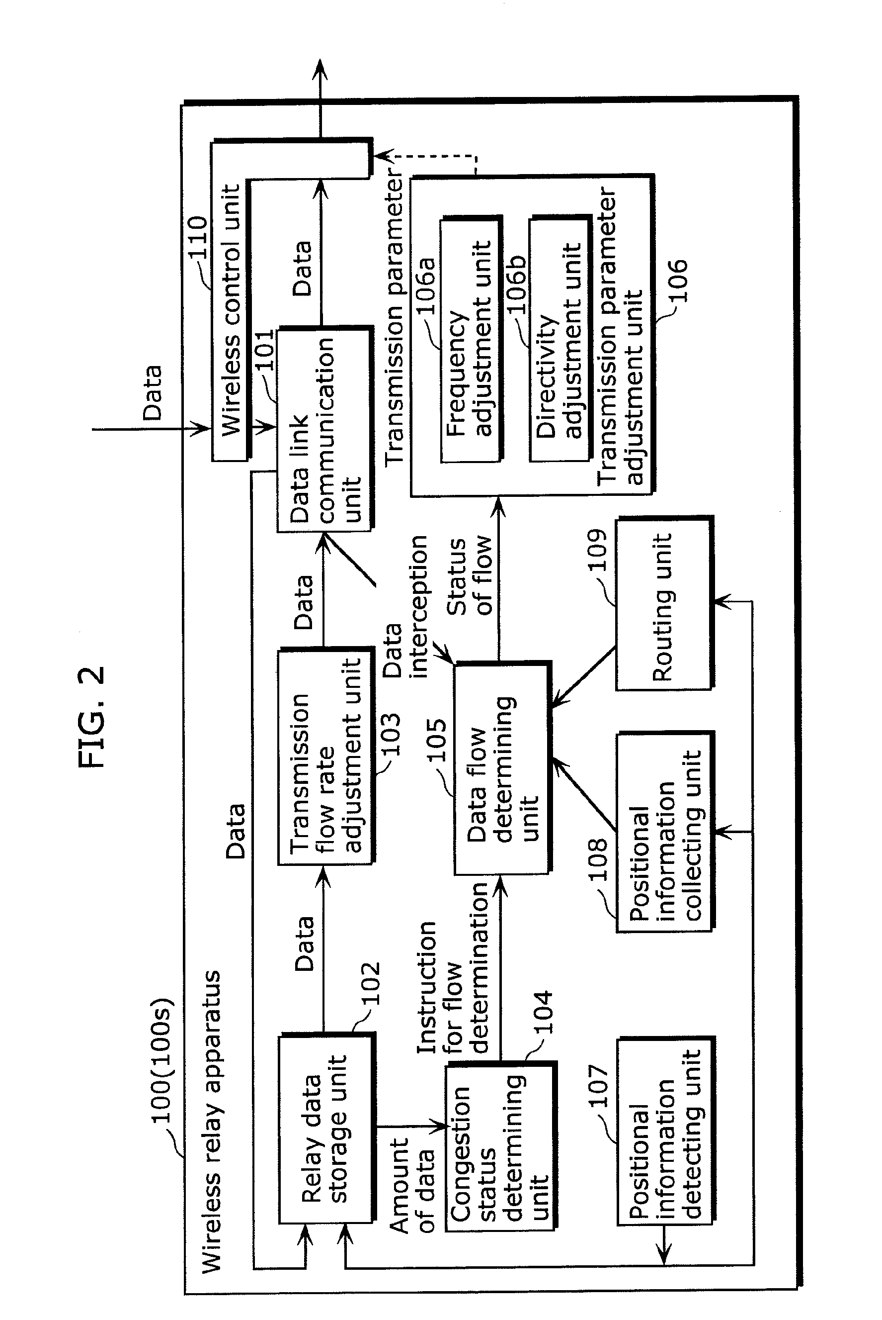
The wireless relay apparatus (100) capable of high-quality transmission of data includes a wireless control unit (110) and a data link communication unit (101) which wirelessly receive and transmit data wirelessly, a congestion status determining unit (104) which determines whether or not a congestion caused by radio wave interference occurs in the wireless relay apparatus (100), a data flow determining unit (105) which identifies a flow of data transmitted and received by the wireless relay apparatus (100) and determines whether the flows intersect in the wireless relay apparatus (100), when the congestion status determining unit (104) determines that there is a congestion, and a transmission parameter adjustment unit (106) which adjust transmission characteristics of a type according to a result of the determination by the data flow determining unit (105), among types of transmission characteristics of radio used in at least one of the wireless control unit (110) and the communication apparatuses (100).
Description
TECHNICAL FIELD[0001]The present invention relates to a wireless relay apparatus included in a network having a wireless network configuration which can be dynamically modified, and to a wireless relay method performed by the wireless relay apparatus.BACKGROUND ART[0002]In a wireless Local Area Network (LAN) which is configured with only the terminals that does not require an access point and capable of establishing wireless connection, the network configuration can be dynamically modified. Such a network is generally referred to as an ad-hoc network or a mesh network.[0003]Terminals that can establish wireless connection in the network include, for example, personal computers, Persona Digital Assistants (PDA), mobile phones, and terminals for on-vehicle car navigation system.[0004]FIGS. 15A and 15B are diagrams showing examples of networks having a wireless network configuration which can be dynamically modified.[0005]Such a network includes, as shown in FIG. 15A, monitoring camera...
Claims
Application Information
Patent Timeline
Application Date:The date an application was filed.
Publication Date:The date a patent or application was officially published.
First Publication Date:The earliest publication date of a patent with the same application number.
Issue Date:Publication date of the patent grant document.
PCT Entry Date:The Entry date of PCT National Phase.
Estimated Expiry Date:The statutory expiry date of a patent right according to the Patent Law, and it is the longest term of protection that the patent right can achieve without the termination of the patent right due to other reasons(Term extension factor has been taken into account ).
Invalid Date:Actual expiry date is based on effective date or publication date of legal transaction data of invalid patent.
