Check patentability & draft patents in minutes with Patsnap Eureka AI!

Vertebral osteosynthesis equipment

a technology of vertebral osteosynthesis and equipment, applied in the field of vertebral osteosynthesis equipment, can solve the problems of affecting the installation of equipment, affecting the effect of equipment maintenance, and consuming a lot of tim

Inactive Publication Date: 2010-09-23
MEDICREA TECH
View PDF5 Cites 32 Cited by
  • Summary
  • Abstract
  • Description
  • Claims
  • Application Information

AI Technical Summary

Benefits of technology

This design significantly simplifies the implantation process, facilitates the shaping of linking rods, and provides robust clamping resistance to repeated loads, making the equipment easier and faster to install while ensuring precise and durable fixation.

Problems solved by technology

Successive insertions and retractions of the extension pieces and successive running down operations of the assemblies composed of connecting parts—linking rods along the latter, then withdrawing the extension pieces for placing the nuts, are then relatively tedious and time-consuming operations.
Moreover, with polyaxial anchoring members, the movements of the proximal studs modify the positions of the connecting parts and disturb consequently the determination of the form which should be given to the linking rod(s) so that these rods may be engaged in these connecting parts, which disturbs noticeably the installation of the equipment.

Method used


Image

  • Vertebral osteosynthesis equipment
  • Vertebral osteosynthesis equipment
  • Vertebral osteosynthesis equipment

Examples


second embodiment

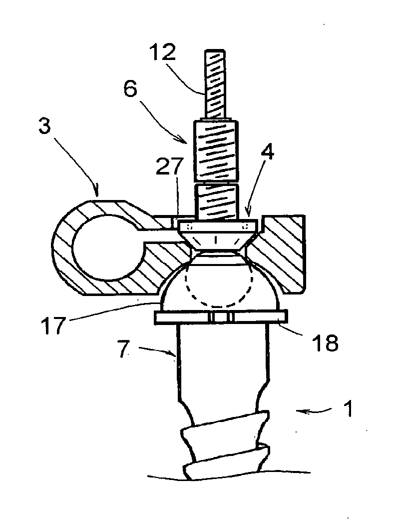
[0061]FIGS. 5 and 6 show a connecting part 3 and two nuts 4, 5 according to the

[0062]In such a case, the nut 4 exhibits a circular external shape and has an external diameter smaller than that of the hole 27 of the proximal branch 22, which enables consequently the nut 4 to run therethrough, without this nut 4 resting against the branch 22.

[0063]The distal branch 21 comprises a hole of diameter smaller than that of the nut 4, so that this nut 4 rests, when screwed on the stud 6, solely against this distal branch 21.

[0064]The nut 5 also exhibits a circular external form and has a diameter greater than that of the hole 27, so that it rests against the branch 22 when clamped around the stud 6. It therefore clamps both branches 21, 22 and immobilises the linking rod 2.

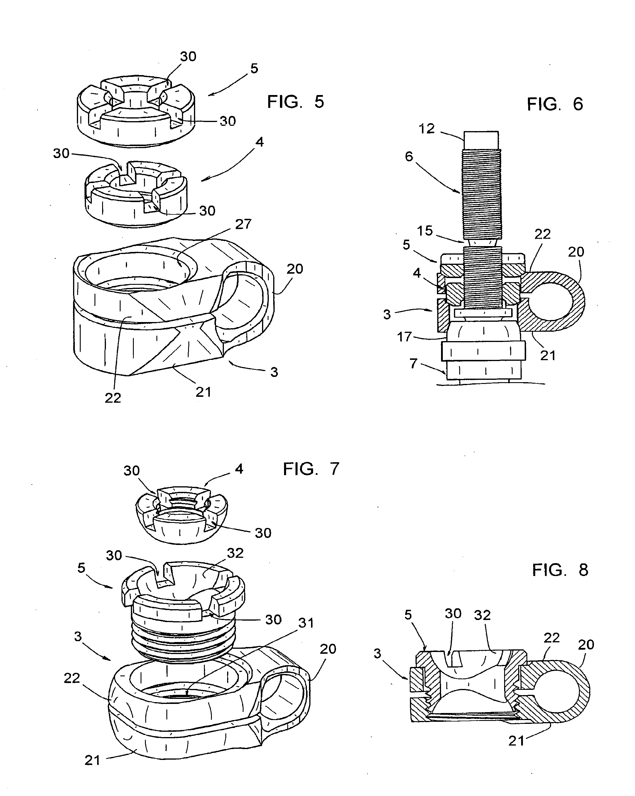
[0065]For their rotational manoeuvres, the nuts 4 and 5 each comprise four radial notches 30, which can accommodate the complementary teeth of a screwing tool.

third embodiment

[0066]FIGS. 7 and 8 show a connecting part 3, a nut 4 and a screw 5 according to the

[0067]In such a case, the distal branch 21 exhibits a tapered bore 31 for screwing the screw 5 and the proximal branch 22 exhibits a hole of diameter greater than the threaded body of this screw 5 but smaller than the diameter of the head of this screw 5.

[0068]The nut 4 has an external form as a portion of a sphere and comprises notches 30 for its rotational manoeuvre.

[0069]The screw 5 exhibits a threaded body for screwing in the tapered bore 31 and a circular screw head resting against the proximal branch 22. This head comprises four notches 30 and a cavity 32 as a portion of a hollow sphere, intended for accommodating the nut 4.

[0070]The screw 5 is tubular and exhibits an axial bore of diameter greater than that of the stud 6, so that the connecting part 3 may, when it includes the screw 5, be engaged on this stud 6.

[0071]Thanks to the screw 5, the connecting part 3 may be clamped on the linking ro...


PUM


Abstract

Equipment includes bony anchoring members one or two linking rods, intended to be connected to the anchoring members, and parts for connecting the linking rod(s) to the anchoring members, at least one anchoring member including a proximal threaded stud and a clamping element for assembling a connecting part thereon, the connecting part including a clamping element for immobilizing the linking rod with respect thereto. The connecting part includes a rounded section for hugging a linking rod and two parallel branches having holes enabling engagement on the proximal threaded stud of the anchoring member; and the clamping elements may be engaged coaxially on the proximal threaded stud of the anchoring member, a first clamping element enabling the assembly of the connecting part on this proximal threaded stud and the second clamping element enabling to clamp both branches of this connecting part.

Description

CROSS REFERENCE TO RELATED APPLICATIONS[0001]This application is a divisional of co-pending application Ser. No. 11 / 312,428 filed on Dec. 21, 2005, which is a CIP of International PCT / IB04 / 02371 filed on Jun. 24, 2004, which claims priority to French Application No. 03 / 07778 filed on Jun. 27, 2003 and U.S. Provisional application No. 60 / 490,518 filed on Jul. 29, 2003. The entire contents of each of the above-identified applications are hereby incorporated by reference.BACKGROUND OF THE INVENTION[0002]1. Field of the Invention[0003]The present invention relates to a vertebral osteosynthesis equipment.[0004]2. Description of the Related Art[0005]A vertebral osteosynthesis equipment generally includes bony anchoring members, such as pedicular screws or hooks, one or two linking rods, intended to be connected to these anchoring members and to be attached to the vertebrae by dint thereof, and parts for connecting this(these) linking rod(s) to these anchoring members. The equipment may al...

Claims


Application Information

Patent Timeline
Patent Type & Authority Applications(United States)
IPC IPC(8): A61B17/70A61B17/86A61B19/00
CPCA61B17/7037A61B2019/307A61B17/8665A61B17/7041A61B2090/037
Inventor CLEMENT, JEAN-LUCFIERE, VINCENTTAYLORADAM, YVESVILLARET, BERNARD
Owner MEDICREA TECH
Features
  • R&D
  • Intellectual Property
  • Life Sciences
  • Materials
  • Tech Scout
  • Unparalleled Data Quality
  • Higher Quality Content
  • 60% Fewer Hallucinations
Learn More