
Drip-style coffee maker

Inactive Publication Date: 2011-02-24
REBECCA LIN INT CORP
View PDF11 Cites 2 Cited by
  • Summary
  • Abstract
  • Description
  • Claims
  • Application Information

AI Technical Summary

Benefits of technology

[0008]This primary objective of the present invention is to provide a drip-style coffee maker which will make coffee grounds soaked evenly.

Problems solved by technology

Under this condition, coffee grounds right under the pipe will be overly soaked, and therefore produces bitter flavor.

Method used


Image

  • Drip-style coffee maker
  • Drip-style coffee maker
  • Drip-style coffee maker

Examples


Embodiment Construction

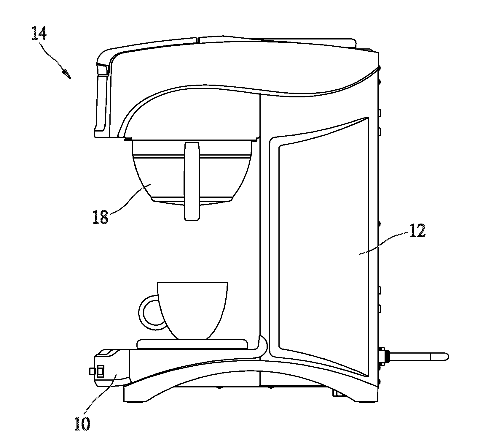
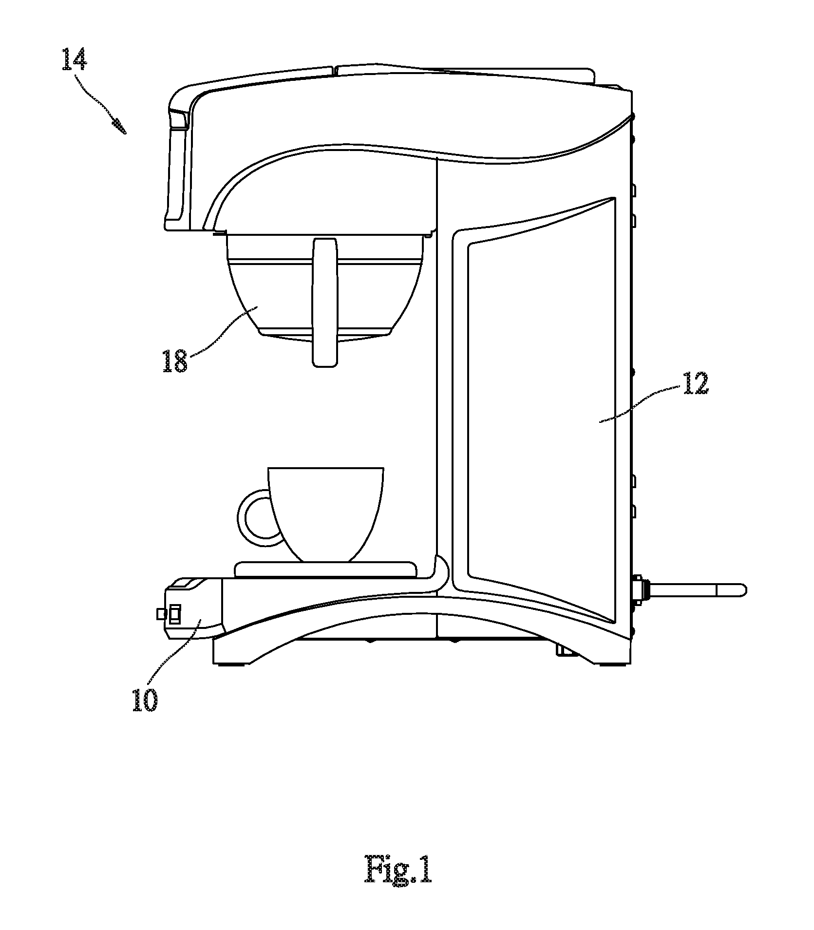
[0015]As shown in FIG. 1 to FIG. 4, a drip-style coffee maker of the preferred embodiment of the present invention includes a stand 10, a frame 12 projected from a top of the stand 10, and a brewing device 14 on the frame 12. The brewing device 14 is provided with a water reservoir (not shown) therein, a heater (not shown), a hot water pipe 16, and a brewing container 18. A filter 20 may be put in the brewing container 18, and coffee grounds 22 are filled in the filter 20. The above devices are the same as the conventional drip-style coffee maker, and we will not describe the details here.

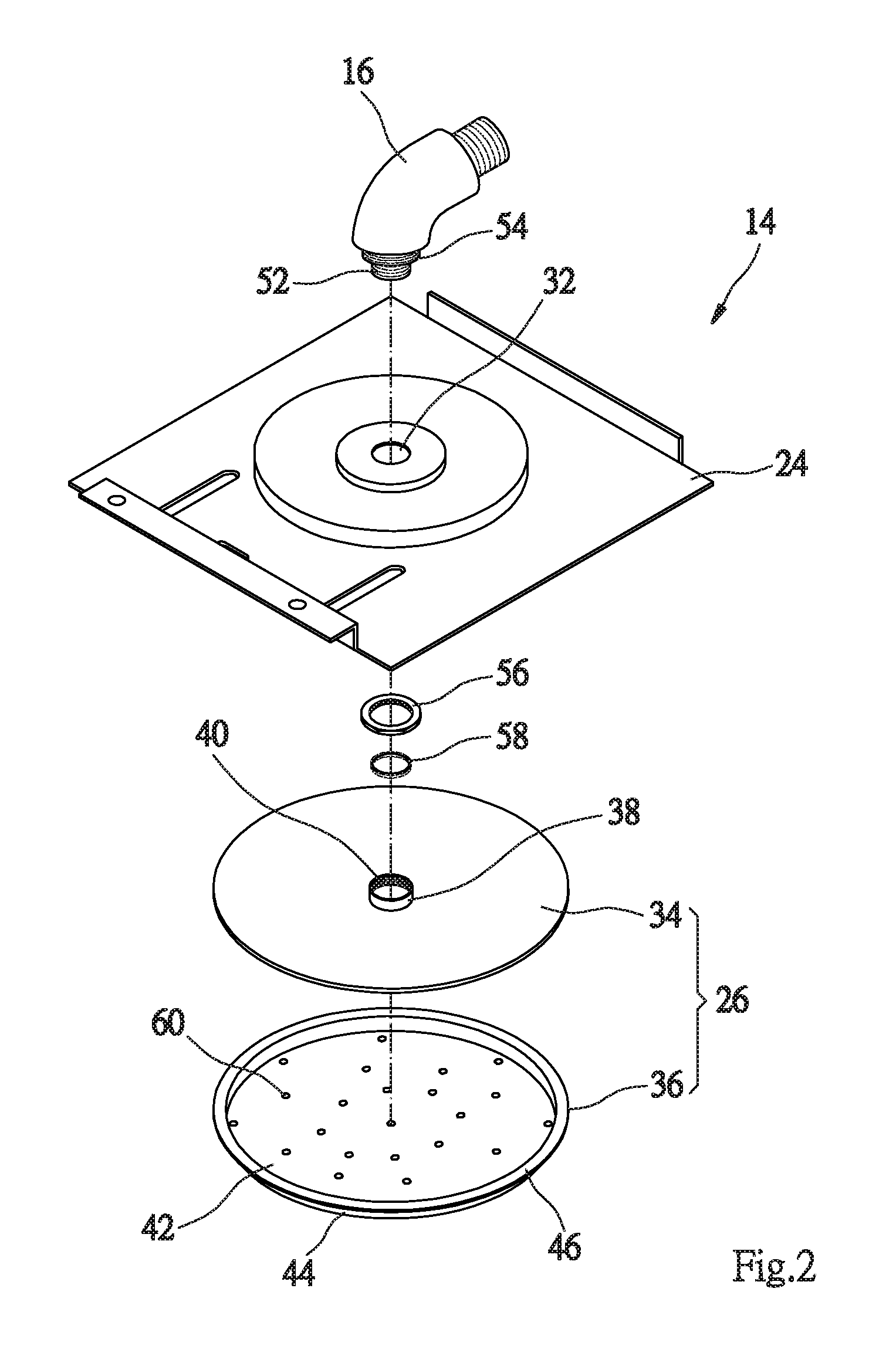
[0016]As shown in FIG. 2 and FIG. 3, the brewing device 14 further includes a base 24 and a spray member 26.

[0017]The base 24 is a plate with a two-staged round protrusion and a first space 28 and a second space 30 are formed under the base 24. The first space 28 has a greater volume, and the second space 30 is at a center of a bottom of the first space. The base 24 has an opening 32 communicated w...


PUM


Abstract

A drip-style coffee maker includes a stand, a frame projected from the stand and a brewing device on the frame. The brewing device includes a hot water pipe having a spout, a brewing container under the spout of the hot water pipe, and a spray member connected to the spout of the hot water pipe. The spray member has a bottom plate and a plurality of apertures distributed on the bottom plate. A diameter of the spray member is equal to or greater than 45% of a maximum diameter of the brewing container that coffee grounds received in the brewing container maybe brewed in a consistent brewing condition.

Description

BACKGROUND OF THE INVENTION[0001]1. Field of the Invention[0002]The present invention relates generally to a coffee maker, and more particularly to a drip-style coffee maker which brews coffee of good flavor and consistent quality.[0003]2. Description of the Related Art[0004]Drip-style coffee maker is a popular coffee making device which is easy to operate and brews coffee of good quality and flavor.[0005]FIG. 5 shows a conventional drip-style coffee maker 70. It includes a base 72, which has an extended frame 74, and a brewing device 76 on its top. The brewing device 76 has a hot water pipe 78, and a container 80 which has a brewing chamber 82. The brewing chamber 82 is provided with filter paper 84. Coffee grounds 86 is filled up into the brewing chamber 82. When hot water flows through water pipe 78 into the brewing chamber 82, it is mixed with the coffee grounds 86, filtered by filter paper 84, and then flows out from an spout 88 at the button of the container 80, and finally in...

Claims


Application Information

Patent Timeline
IPC IPC(8): A47J31/057A47J31/46
CPCA47J31/4478
Inventor LIN, HSUEH-YU
Owner REBECCA LIN INT CORP
Learn More