
Film deposition device

a technology of film deposition and film, which is applied in the direction of chemical vapor deposition coating, metal material coating process, coating, etc., can solve the problems of reducing the use efficiency and work efficiency of the devi

Inactive Publication Date: 2011-02-24
FUJIFILM CORP
View PDF10 Cites 3 Cited by
  • Summary
  • Abstract
  • Description
  • Claims
  • Application Information

AI Technical Summary

Benefits of technology

[0012]As described in JP 2004-95677 A, in an apparatus which continuously carried out a plurality of treatments on an elongated substrate as it travels, a gas in a treatment room can be prevented from entering its adjacent upstream- and downstream-side treatment rooms by providing differential rooms between the adjacent treatment rooms through which the treatment is continuously carried out and evacuating the differential rooms so that the internal pressure of the differential rooms may be lower than that of the adjacent treatment rooms.
[0027]The pressure of the differential room is set higher than that of the adjacent rooms, thus preventing penetration of a reactive gas for use in CVD into the differential room and also film deposition in the differential room and its contamination. In addition, a gas to be supplied to both the adjacent treatment rooms or an inert gas is supplied to the differential room so that the differential room may have a higher pressure than that of the adjacent rooms, and therefore there is no adverse effect on the CVD film formation or the treatment in the treatment rooms.

Problems solved by technology

Therefore, maintenance including apparatus cleaning requires much time, thus leading to a decrease in the use efficiency and work efficiency of the device.

Method used


Image

  • Film deposition device
  • Film deposition device

Examples


example 1

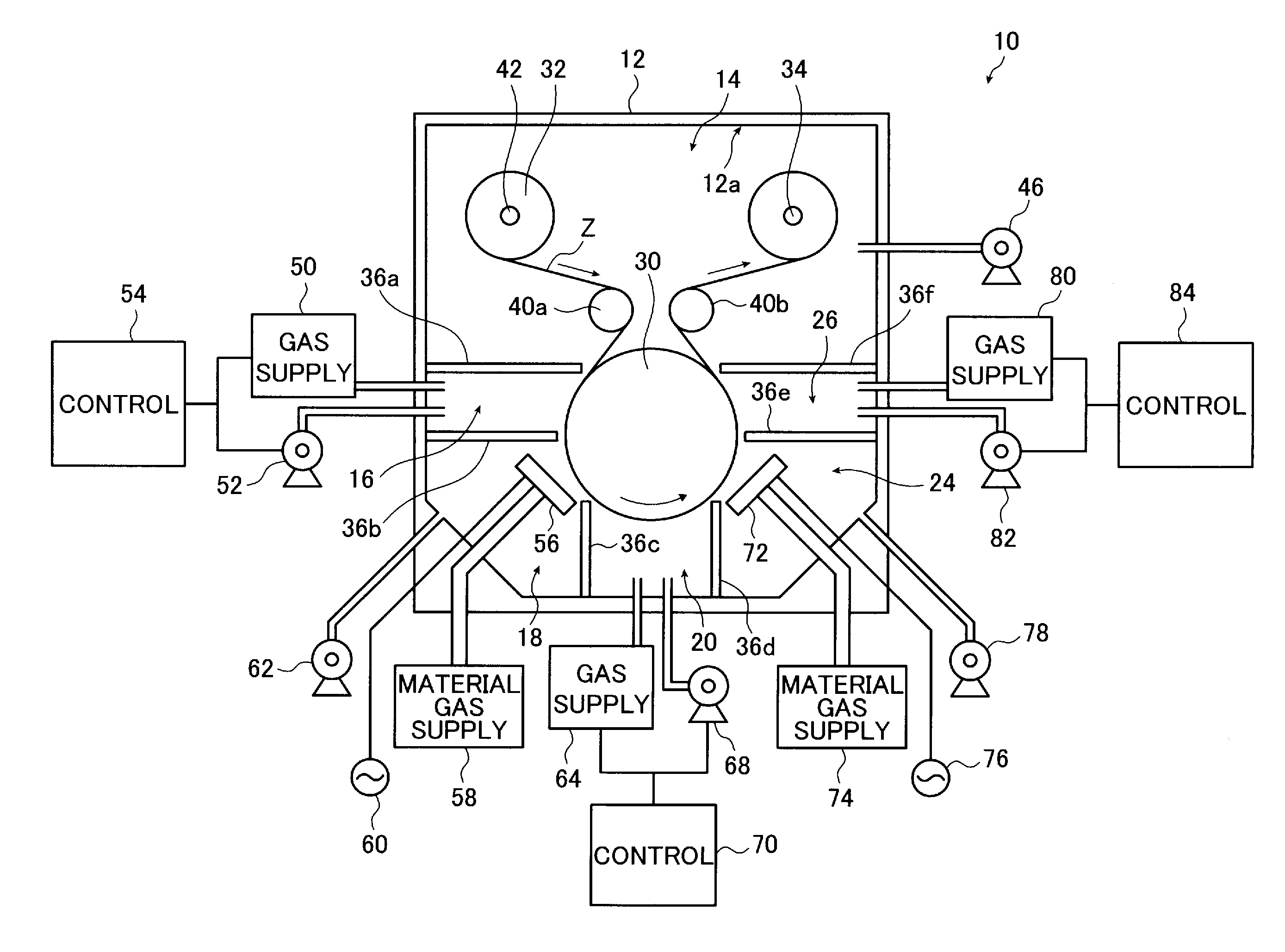
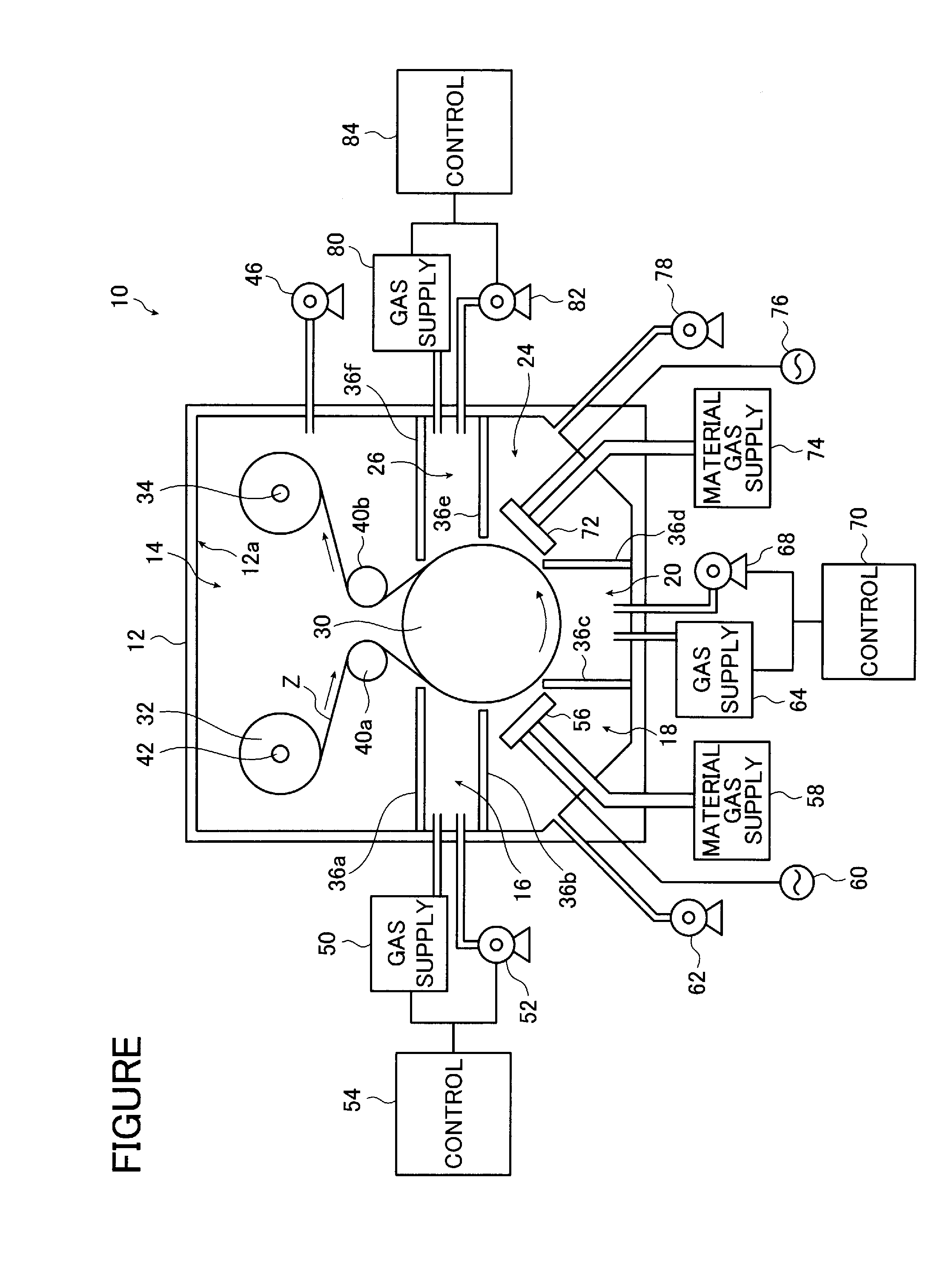
[0125]The film deposition device 10 shown in the FIGURE was used to deposit a silicon nitride film on a substrate Z.

[0126]The substrate Z used was a PET film (Cosmoshine A4300 available from Toyobo Co., Ltd.).

[0127]Silane gas (at a flow rate of 100 sccm), ammonia gas (at a flow rate of 100 sccm) and nitrogen gas (at a flow rate of 800 sccm) were used as the material gases to form the silicon nitride film by means of CCP-CVD. The gas used to supply to the differential rooms was nitrogen gas (at a flow rate of 1000 sccm).

[0128]The film deposition pressure of the first film deposition room 18 and the second film deposition room 24 was set to 30 Pa and 20 Pa, respectively, and the first differential room 16 and the second differential room 20 were set to a pressure of 35 Pa, whereas the third differential room 26 was set to a pressure of 25 Pa.

[0129]In addition, the power sources used were RF power sources at a frequency of 13.56 MHz and the plasma excitation power supplied to the showe...


PUM

PropertyMeasurementUnit
pressureaaaaaaaaaa
pressureaaaaaaaaaa
pressureaaaaaaaaaa

Abstract

The film deposition device includes a CVD film forming room disposed on a travel path of a substrate and having a function of performing the film deposition on a substrate by CVD, a treatment room disposed upstream or downstream of the CVD film forming room on the travel path and having a function of performing a predetermined treatment on the substrate, and a differential room disposed between and communicating with the CVD film forming room and the treatment room. The differential room includes a evacuation unit, a gas introducing unit for introducing at least one of a gas to be supplied to both of the CVD film forming room and the treatment room, and an inert gas, and a controller which controls the evacuation unit and the gas introducing unit to keep the differential room at a higher pressure than the CVD film forming room and the treatment room.

Description

BACKGROUND OF THE INVENTION[0001]The present invention relates to a film deposition device suitable to produce gas barrier films. The present invention more specifically relates to a film deposition device in which a plurality of treatments including film formation by means of CVD are continuously carried out as an elongated substrate travels, and which can eliminate adverse effects of the pressure in the other treatment rooms and material gases while also suppressing contamination of the device with the material gases used in CVD.[0002]Various functional films (functional sheets) including gas barrier films, protective films, and optical films such as optical filters and antireflection films are used in various devices including optical devices, display devices such as liquid crystal displays and organic EL displays, semiconductor devices, and thin-film solar batteries.[0003]These functional films have been produced by film formation (thin film formation) through vacuum deposition ...

Claims


Application Information

Patent Timeline
Patent Type & Authority Applications(United States)
IPC IPC(8): C23C16/52
CPCC23C16/545C23C16/45519
Inventor FUJINAMI, TATSUYATAKAHASHI, SHINSUKETONOHARA, KOUJIFUJINAWA, JUN
Owner FUJIFILM CORP
Learn More