Supercharge Your Innovation With Domain-Expert AI Agents!

DC offset cancellation circuit

a cancellation circuit and offset technology, applied in the direction of pulse automatic control, amplifiers with semiconductor devices/discharge tubes, amplifiers, etc., can solve the problems of complicated and difficult design of dc offset cancellation circuits

Active Publication Date: 2011-05-26
ELECTRONICS & TELECOMM RES INST
View PDF3 Cites 9 Cited by
  • Summary
  • Abstract
  • Description
  • Claims
  • Application Information

AI Technical Summary

Benefits of technology

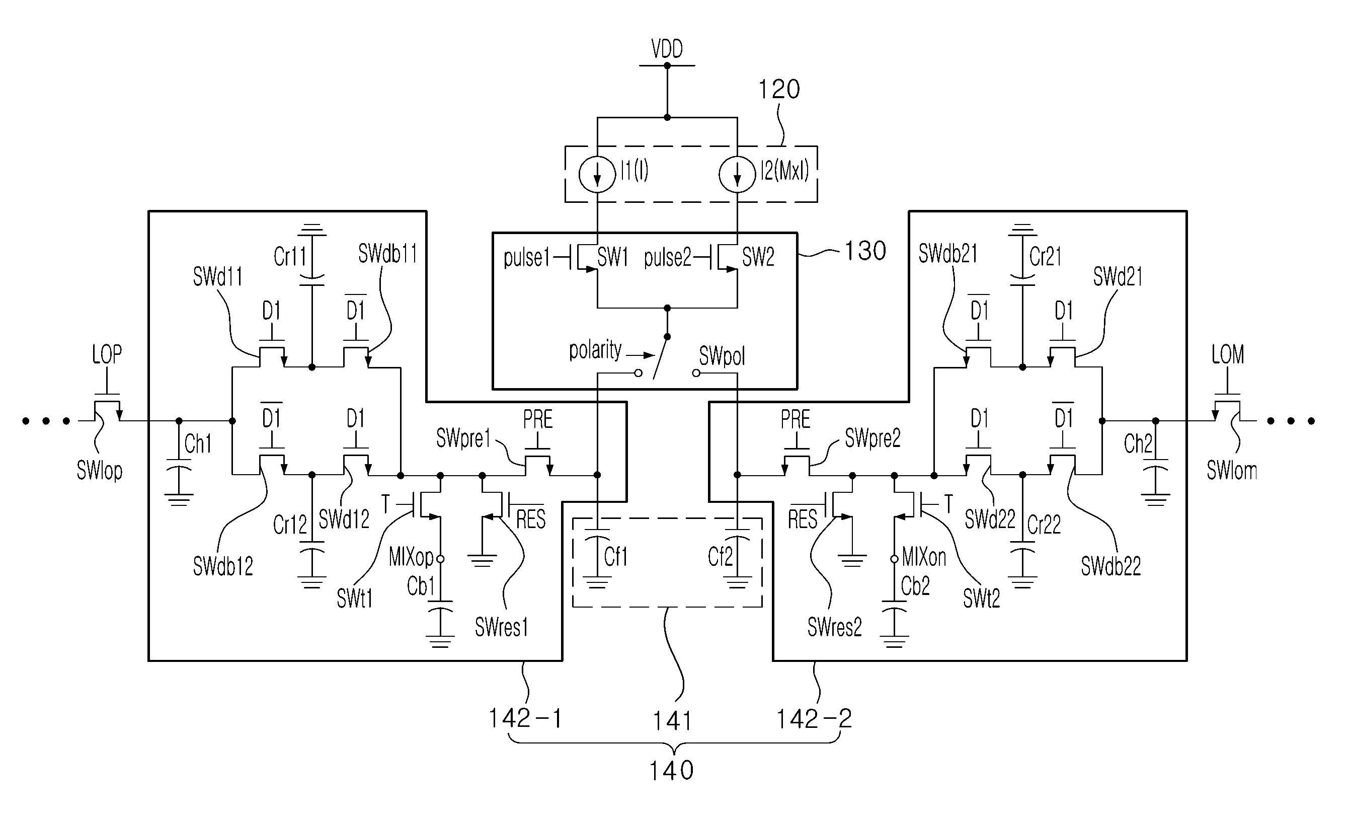
The present invention provides a DC offset cancellation circuit that can adjust the DC offset without using a current type digital-to-analog converter or a sigma-delta converter. The circuit can extend the DC offset adjustment range and has low-noise characteristics. It includes a control signal generation unit, a current source supplying current, a switching unit, an electric charge quantity regulation unit, and a DC offset adjustment circuit. The control signal generation unit generates pulse signals with different pulse widths to adjust the DC offset. The current source supplies current with different current ratios to the feedback capacitor. The switching unit determines the current quantity to be supplied to the feedback capacitor by adjusting the pulse width of the reference clock. The electric charge quantity regulation unit charges the DC offset electric charges and transfers them to the sampling capacitor. The DC offset cancellation circuit can be used in a DC offset cancellation system.

Problems solved by technology

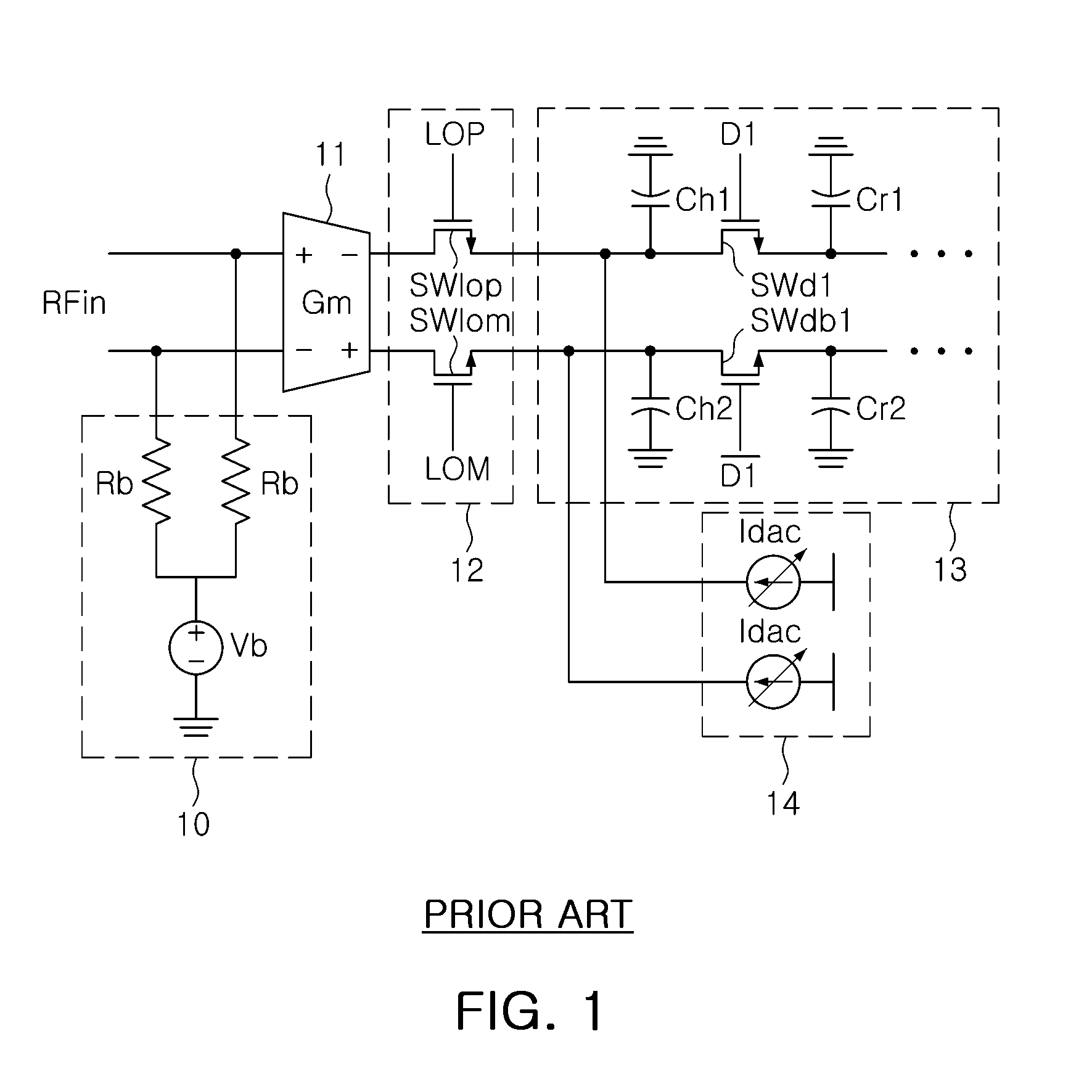
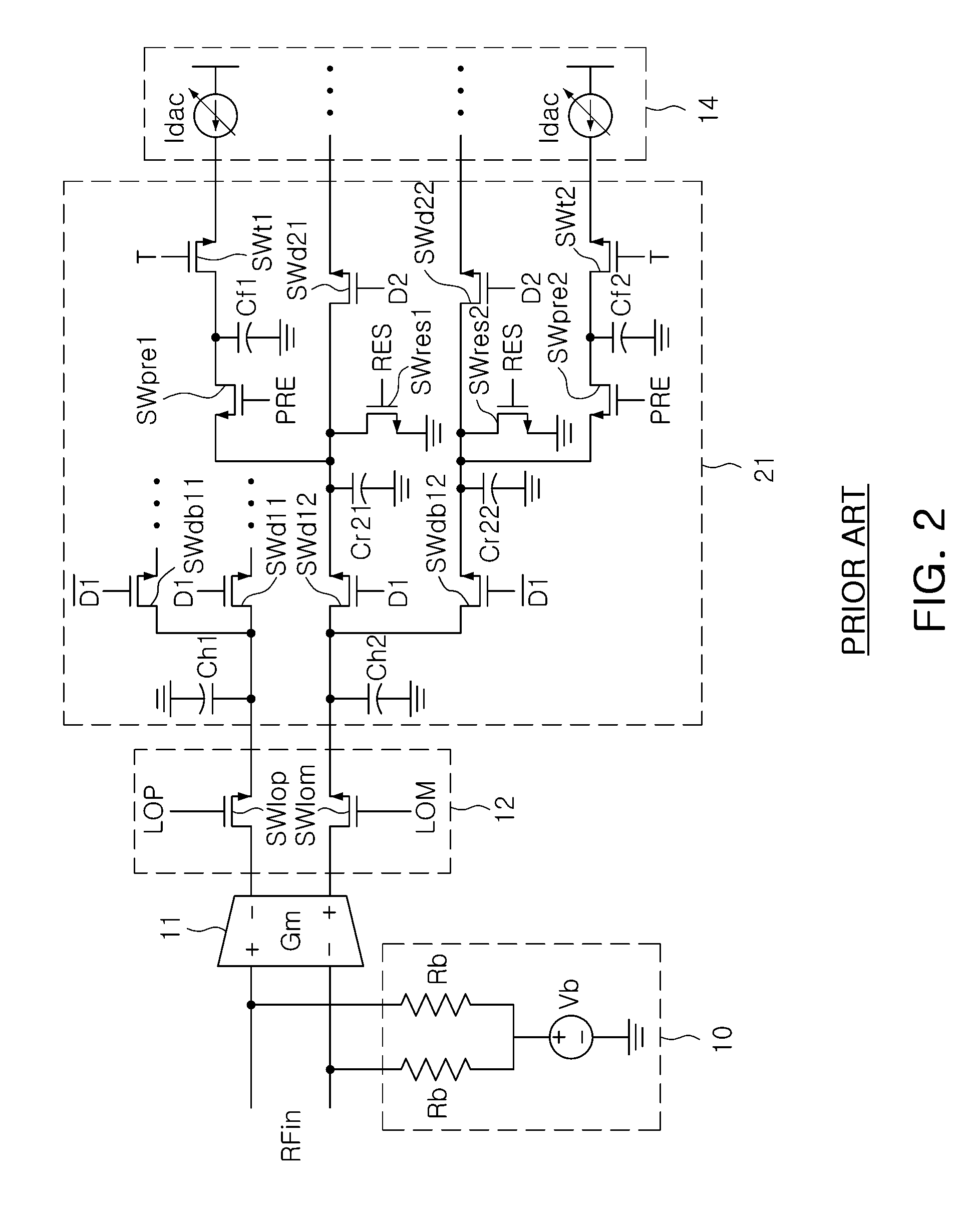
In this case, in order to minutely adjust the DC offset electric charges, the resolution of the current type digital-to-converter must be increased, a factor that makes the designing thereof complicated and difficult.
As a result, in order to minutely adjust the DC offset in the related art, the current type digital-to-analog converter having high resolution or the sigma-delta converter using the high frequency clock must be provided, and this makes the designing of the DC offset cancellation circuit complicated and difficult.

Method used


Image

  • DC offset cancellation circuit
  • DC offset cancellation circuit
  • DC offset cancellation circuit

Examples


Embodiment Construction

[0046]As the present invention allows for various changes and numerous embodiments, particular embodiments will be illustrated in drawings and described in detail in the written description.

[0047]However, this is not intended to limit the present invention to particular modes of practice, and it is to be appreciated that all changes, equivalents, and substitutes that do not depart from the spirit and technical scope of the present invention are encompassed in the present invention.

[0048]While such terms as “first” and “second,” etc., may be used to describe various components, such components must not be limited to the above terms. The above terms are used only to distinguish one component from another. For example, a first component may be referred to as a second component without departing from the scope of the rights of the present invention, and likewise, a second component may be referred to as a first component.

[0049]When a component is mentioned to be “connected” to or “acces...


PUM


Abstract

A DC offset cancellation circuit includes: a control signal generation unit generating i (i is a natural number) number of pulse signals having a pulse width corresponding to a DC offset amount; a current source supplying i number of currents each having a different current ratio; a switching unit determining a current quantity to be supplied to a feedback capacitor by adjusting a turn-on quantity of each of the i number of currents according to the pulse width of each of the i number of pulse signals; and an electric charge quantity regulation unit charging DC offset electric charges corresponding to current supplied from the switching unit through the feedback capacitor and transferring the DC offset electric charges charged in the feedback capacitor to a sampling capacitor through a rotary capacitor, to allow the sampling capacitor to primarily store the DC offset electric charges and then secondarily store electric charges corresponding to an input signal. s

Description

CROSS-REFERENCE TO RELATED APPLICATIONS[0001]This application claims the priorities of Korean Patent Application Nos. 10-2009-0112802 filed on Nov. 20, 2009 and 10-2010-0026184 filed on Mar. 24, 2010, in the Korean Intellectual Property Office, the disclosures of which are incorporated herein by reference.BACKGROUND OF THE INVENTION[0002]1. Field of the Invention[0003]The present invention relates to a DC offset cancellation circuit and more particularly, to a DC offset cancellation circuit for a discrete time receiver capable of minutely adjusting a DC offset and extending a DC offset adjustment range.[0004]2. Description of the Related Art[0005]Because a discrete time filter involves the occurrence of an LO (Local Oscillator) leakage and includes a switch and a capacitor, a DC offset is easily generated, so the discrete time filter requires a supplementary circuit such as a DC offset cancellation circuit in order to cancel the DC offset, and in this case, it is very significant fo...

Claims


Application Information

Patent Timeline
Patent Type & Authority Applications(United States)
IPC IPC(8): H03L5/00
CPCH03F3/45968H03M1/822H03F2203/45212
Inventor LEE, YOUNG JAELEE, SANG SUNGLEE, SNAG-GUN
Owner ELECTRONICS & TELECOMM RES INST
Features
  • R&D
  • Intellectual Property
  • Life Sciences
  • Materials
  • Tech Scout
  • Unparalleled Data Quality
  • Higher Quality Content
  • 60% Fewer Hallucinations
Learn More