
Catalytic Converter for a Pulse Detonation Turbine Engine

Inactive Publication Date: 2012-08-02
GENERAL ELECTRIC CO
View PDF17 Cites 4 Cited by
  • Summary
  • Abstract
  • Description
  • Claims
  • Application Information

AI Technical Summary

Benefits of technology

[0006]The present application further provides a method of minimizing or eliminating one or more undesirable emissions in a flow of combustion gases in a pulse detonation turbine engine. The method may include the steps of generating the flow of combustion gases with the undesirable emission therein in one or more pulse detonation combustors, driving a turbine with the flow of combustion gases, and passing the flow of combustion gases through a catalytic converter to minimize or eliminate the undesirable emissions contained therein.

Problems solved by technology

Undesirable emissions, however, currently may be an issue for any combustion process other than deflagration.
Even when the chemical reactions reach equilibrium in a detonative combustion process, undesirable emissions such as carbon monoxide (CO) and nitrogen oxides (NOx) may be present at levels higher than produced by a comparable constant pressure combustor.
Moreover, these emissions generally reduce the combustion efficiency of the pulse detonation combustor in a pulse detonation turbine engine.
A reduction in levels of emissions such as carbon monoxide and nit oxides thus is an issue in the adaptation of a pulse detonation turbine engine as an energy / propulsion conversion device.

Method used


Image

  • Catalytic Converter for a Pulse Detonation Turbine Engine
  • Catalytic Converter for a Pulse Detonation Turbine Engine
  • Catalytic Converter for a Pulse Detonation Turbine Engine

Examples


Embodiment Construction

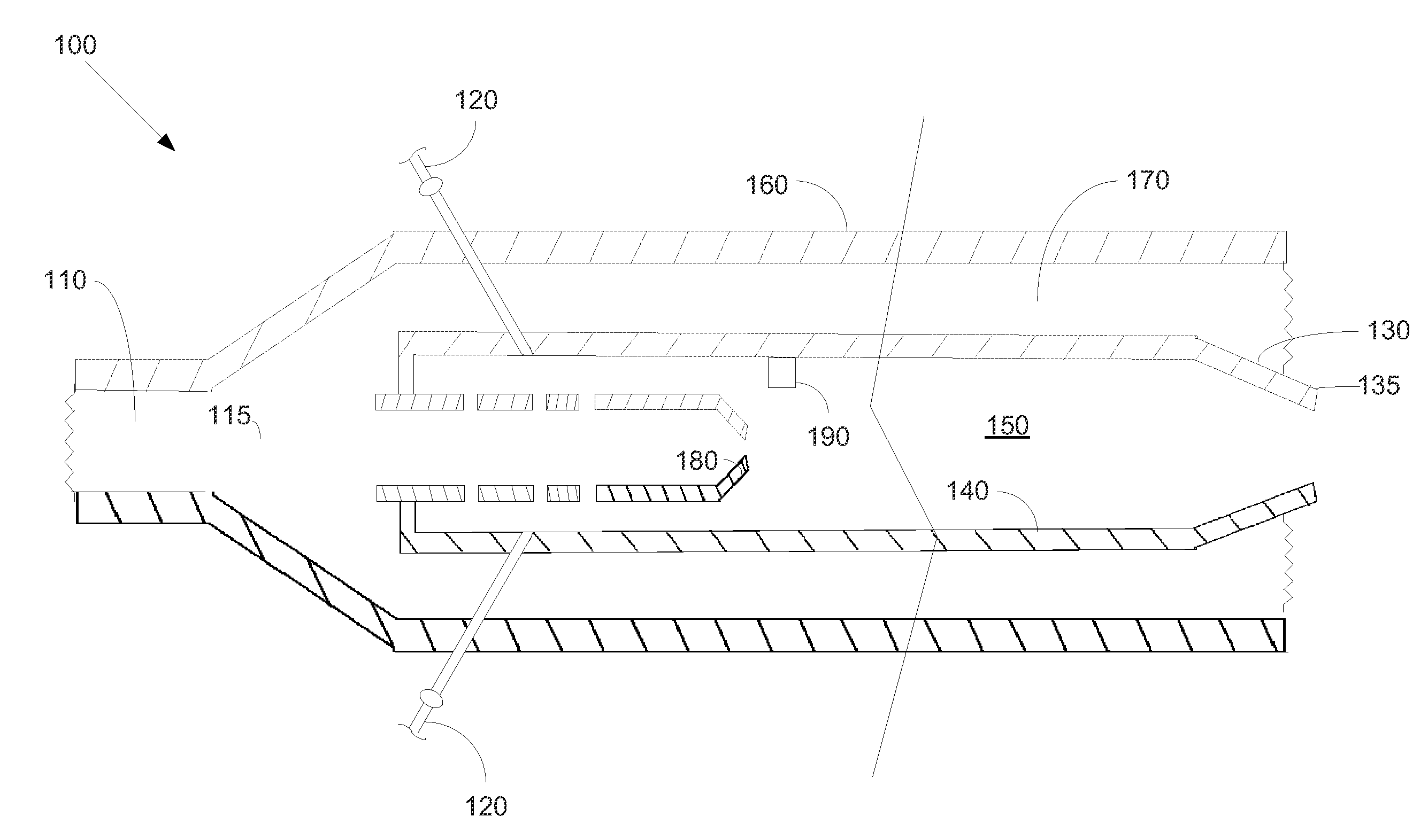
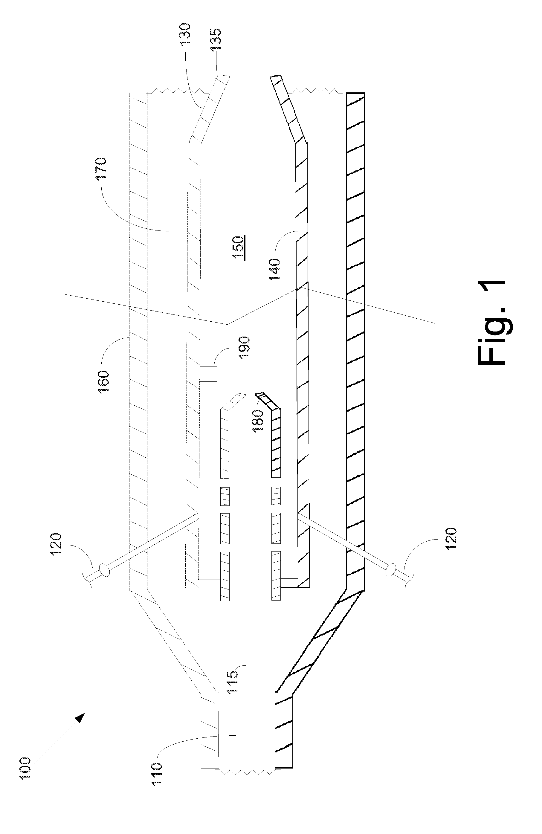
[0013]As used herein, the term “pulse detonation combustor” refers to a device or a system that produces both a pressure rise and a velocity increase from the detonation or quasi-detonation of a fuel and an oxidizer. The pulse detonation combustor may be operated in a repeating mode to produce multiple detonations or quasi-detonations within the device. A “detonation” may be a supersonic combustion in which a shock wave is coupled to a combustion zone. The shock may be sustained by the energy release from the combustion zone so as to result in combustion products at a higher pressure than the combustion reactants. A “quasi-detonation” may be a supersonic turbulent combustion process that produces a pressure rise and a velocity increase higher than the pressure rise and the velocity increase produced by a sub-sonic deflagration wave, i.e., detonation and fast flames. For simplicity, the terms “detonation” or “detonation wave” as used herein will include both detonations and quasi-det...


PUM


Abstract

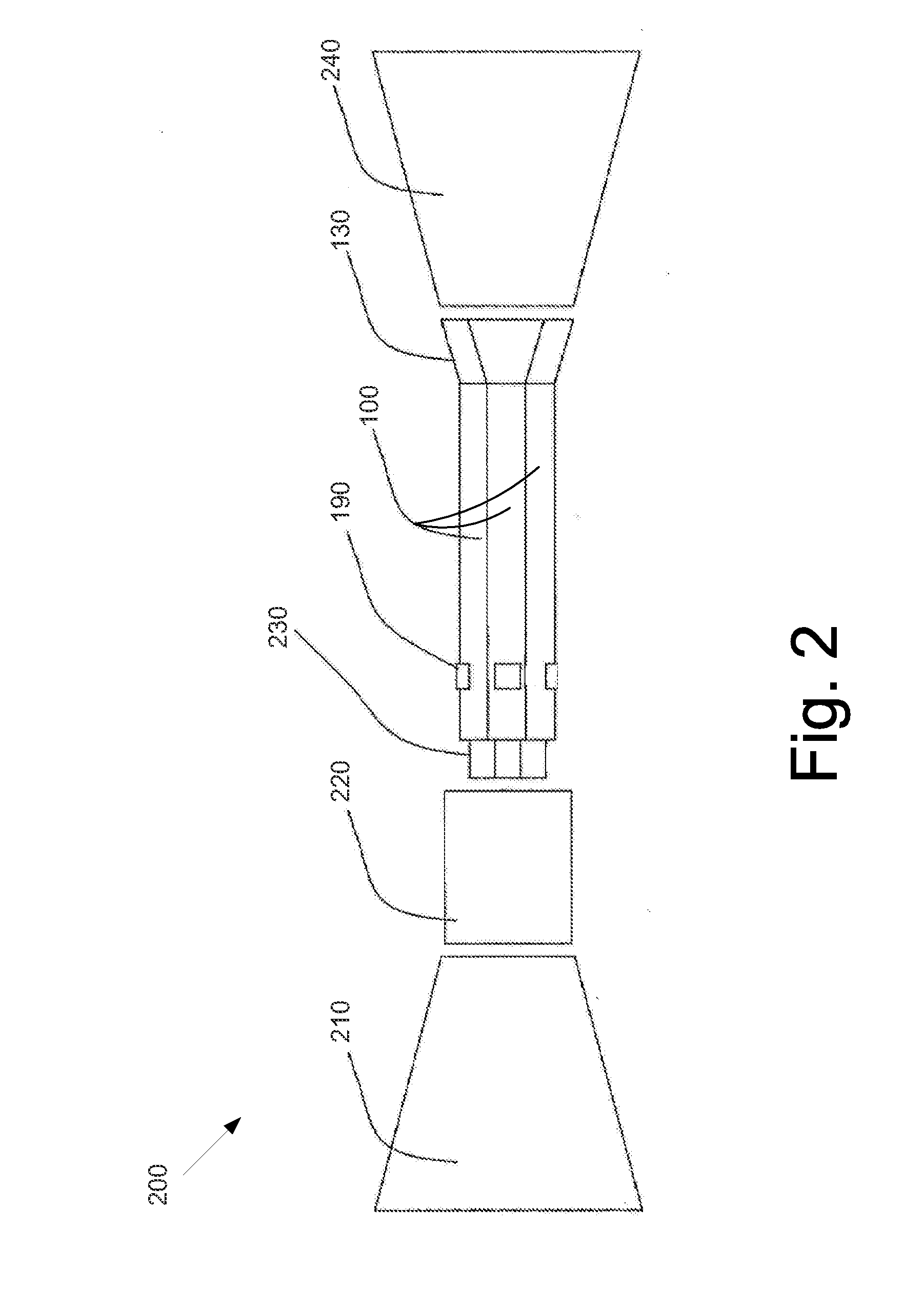
The present application provides a pulse detonation turbine engine. The pulse detonation turbine engine may include one or more pulse detonation combustors to produce a flow of combustion gases, a turbine positioned downstream of the pulse detonation combustors such that the flow of combustion gases drives the turbine, and a catalytic converter positioned downstream of the pulse detonation combustors such that the flow of combustion gases passes therethrough.

Description

TECHNICAL FIELD[0001]The present application relates generally to pulse detonation turbine engines and more particularly relates to a pulse detonation turbine engine with a catalytic converter positioned downstream of one or more pulse detonation combustors to minimize or reduce undesirable emissions therein.BACKGROUND OF THE INVENTION[0002]Recent developments with pulse detonation combustors and engines have focused on practical applications such as generating additional thrust / propulsion for aircraft engines and to improve overall performance in ground-based power generation systems. Known pulse detonation combustors and engines generally operate with a detonation process having a pressure rise as compared to conventional engines operating with a constant pressure deflagration. Specifically, air and fuel are mixed within a pulse detonation chamber and ignited to produce a combustion pressure wave. The combustion pressure wave transitions into a detonation wave followed by combusti...

Claims


Application Information

Patent Timeline
IPC IPC(8): F02K7/02
CPCF02K7/02F02C5/00
Inventor TANGIRALA, VENKAT ESWARLUJOSHI, NARENDRAKALITAN, DANIELLEMA, FUHUALAVERTU, THOMAS
Owner GENERAL ELECTRIC CO
Learn More