Check patentability & draft patents in minutes with Patsnap Eureka AI!

Optical fiber and method and apparatus for manufacturing optical fiber

Active Publication Date: 2012-08-16
THE FUJIKURA CABLE WORKS LTD
View PDF9 Cites 4 Cited by
  • Summary
  • Abstract
  • Description
  • Claims
  • Application Information

AI Technical Summary

Benefits of technology

[0033]In addition, the inventors found that elastic torsion (twist) could be held when the above-described optical fiber was used in end products, such as optical cables, and this could suppress a PMD increases caused by external factors.
[0074]In addition, according to the optical fiber manufacturing method and the optical fiber manufacturing apparatus of the invention, it is possible to reliably and easily manufacture the optical fiber capable of reliably and stably suppressing the PMD increase caused by external factors, such as bending or lateral pressure, as described above.

Problems solved by technology

In addition, if a PMD increases, waveform deterioration occurs in signal light transmitted through the fiber in digital transmission, therefore, it becomes difficult to separate adjacent pulses from each other.
As a result, a problem occurs in that problems arise such as the transmission capacity becoming limited.
On the other hand, in the manufacture of optical fibers, it is difficult in practice to realize a completely circular cross-sectional shape including the core of the optical fiber and the cladding around the core regardless of which fiber preform manufacturing method and method of manufacturing a bare optical fiber by drawing (fiber drawing) a fiber preform are selected.
However, it is known that such a method of giving an optical fiber a span is not effective for suppressing a PMD increase caused by external factors (for example, refer to WO2009 / 107667).

Method used


Image

  • Optical fiber and method and apparatus for manufacturing optical fiber
  • Optical fiber and method and apparatus for manufacturing optical fiber
  • Optical fiber and method and apparatus for manufacturing optical fiber

Examples


first example

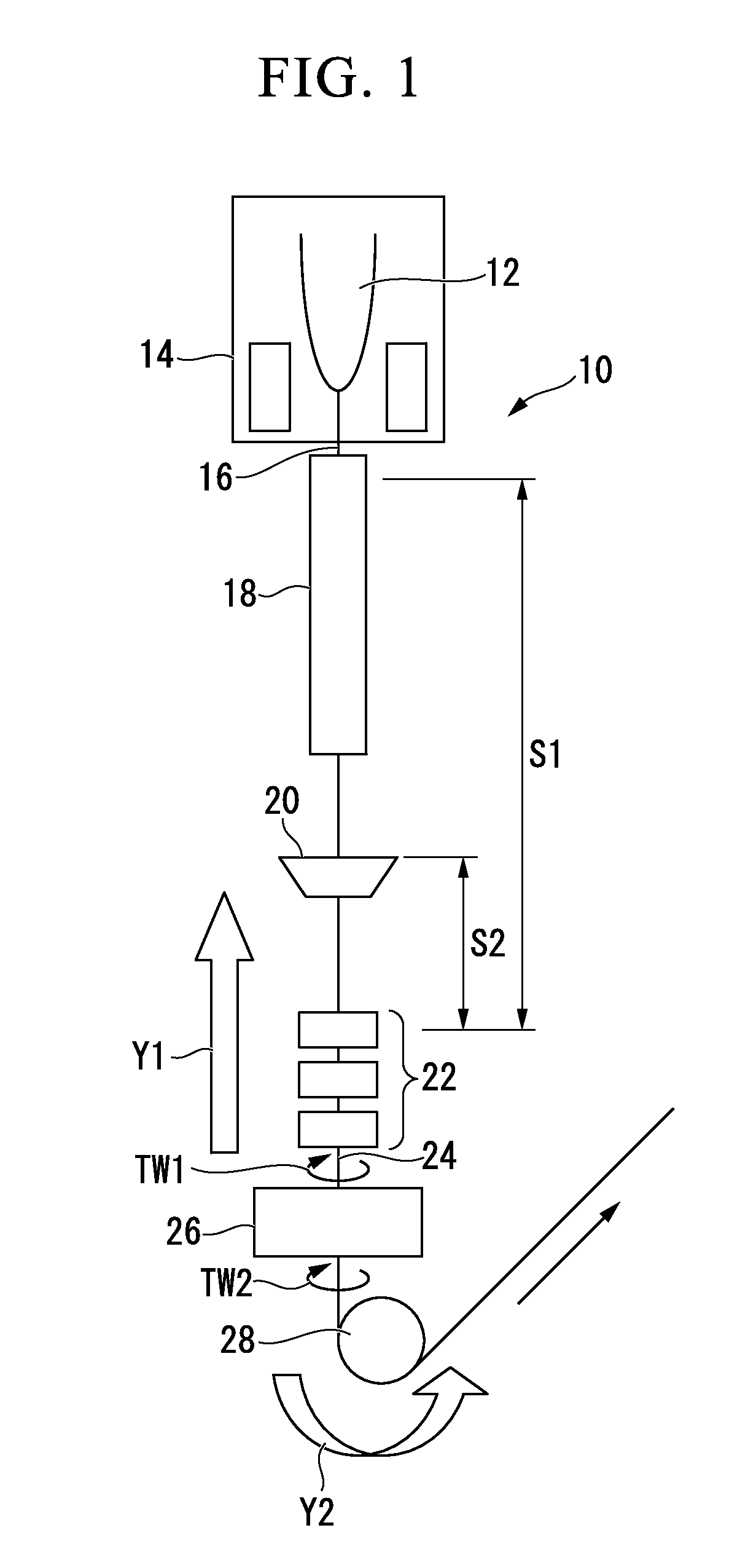
[0195]Using the optical fiber manufacturing apparatus shown in FIG. 1 and using the device shown in FIG. 3 as a twisting device in the manufacturing apparatus, an optical fiber to which elastic torsion (twist) was applied to a silica glass based optical fiber with a two-layer coat structure, which had characteristics of a typical single-mode fiber, according to the above-described method of the invention was manufactured.

[0196]The drawing speed (fiber drawing speed) from the optical fiber preform was set to 2000 mm / min.

[0197]In addition, a two-layer simultaneous coating method (wet on wet method) for coating two kinds of coating resin at one place was applied by the coating device.

[0198]UV curable urethane acrylate based resin (Young's modulus at the time of curing was 0.5 MPa) was used as a resin (primary material) of the first coating layer, and UV curable urethane acrylate based resin (Young's modulus at the time of curing was 1000 MPa) was used as a resin (secondary material) of...

second example

[0234]Using the optical fiber manufacturing apparatus shown in FIG. 8 and using the device shown in FIG. 3 as the twisting device 26 in the manufacturing apparatus, an optical fiber to which elastic torsion (twist) was applied to a silica glass based optical fiber with a two-layer coat structure, which had characteristics of a typical single-mode fiber, according to the above-described method of the invention was manufactured.

[0235]The drawing speed (fiber drawing speed) from the optical fiber preform was set to 1500 mm / min.

[0236]In addition, a method of coating different coating resins at two places (wet on dry method) as shown in FIG. 8 was applied as a coating-curing method.

[0237]A UV curable urethane acrylate based resin (Young's modulus at the time of curing was 1.0 MPa) was used as a resin (primary material) of the first coating layer, and a UV curable urethane acrylate based resin (Young's modulus at the time of curing was 500 MPa) was used as a resin (secondary material) of ...

third example

[0253]An optical fiber with a 2-layer coating structure was manufactured while giving elastic torsion (twist) in the same manner as in the second example.

[0254]In addition, as the viscosity of coating resin at the time of coating (in a liquid state), the viscosity of the primary material was adjusted to 3 Pa·sec and the viscosity of the secondary material was adjusted to 0.1 Pa·sec, in the same manner as in the second example.

[0255]The profile of the torsion in a longitudinal direction of an optical fiber, which was applied to the optical fiber by the twisting device, was a trapezoidal wave which had a periodically reversed torsional direction, and the swing angle and the swing speed of the twisting device were set such that the period T became 30 m and the maximum torsion angle MA of the accumulated torsion angle became 120000°.

[0256]The optical fiber after passing the twisting device was picked up by a pickup device and was wound through a dancer pulley by a winding device. As a r...


PUM

PropertyMeasurementUnit
Lengthaaaaaaaaaa
Viscosityaaaaaaaaaa
Lengthaaaaaaaaaa

Abstract

An optical fiber includes a bare optical fiber portion, to which elastic torsion is applied, and a coating layer, which coats the bare optical fiber portion, is formed of curable resin, and causes elastic repulsion against resilience occurring in the bare optical fiber portion so that the elastic torsion applied to the bare optical fiber portion is held.

Description

BACKGROUND OF THE INVENTION[0001]1. Field of the Invention[0002]The present invention relates to an optical fiber represented by a silica glass based optical fiber and an optical fiber manufacturing method and in particular, to a technique of reducing the polarization mode dispersion (hereinafter, referred to as “PMD”) of an optical fiber. Especially, the invention relates to an optical fiber, in which the amount of increase in PMD is small even if subject to interference, such as lateral pressure or bending, and a method and apparatus for manufacturing optical fiber.[0003]Priority is claimed on Japanese Patent Application No. 2011-028387, filed Feb. 14, 2011, the content of which is incorporated herein by reference.[0004]2. Description of Related Art[0005]As is well known, a PMD is a phenomenon in which a propagation time difference (delay difference) occurs between two orthogonal polarization mode components in an optical fiber.[0006]In addition, if a PMD increases, waveform deter...

Claims


Application Information

Patent Timeline
IPC IPC(8): G02B6/10G02B6/036
CPCC03B37/02745C03B37/032C03B2203/06G02B6/02285C03B2203/19C03B2205/06C03C25/1065C03B2203/18
Inventor OKADA, KENJI
Owner THE FUJIKURA CABLE WORKS LTD
Features
  • R&D
  • Intellectual Property
  • Life Sciences
  • Materials
  • Tech Scout
  • Unparalleled Data Quality
  • Higher Quality Content
  • 60% Fewer Hallucinations
Learn More