Contact feature for use with transducing devices
a technology for transducing devices and contact features, which is applied in the direction of recording information storage, transportation and packaging, instruments, etc., can solve the problems of heat dissipation into the surrounding components of the head, loss of data, and increased possibility of unintentional contact between the magnetic head and the magnetic media
- Summary
- Abstract
- Description
- Claims
- Application Information
AI Technical Summary
Benefits of technology
Problems solved by technology
Method used
Image


Examples
first embodiment
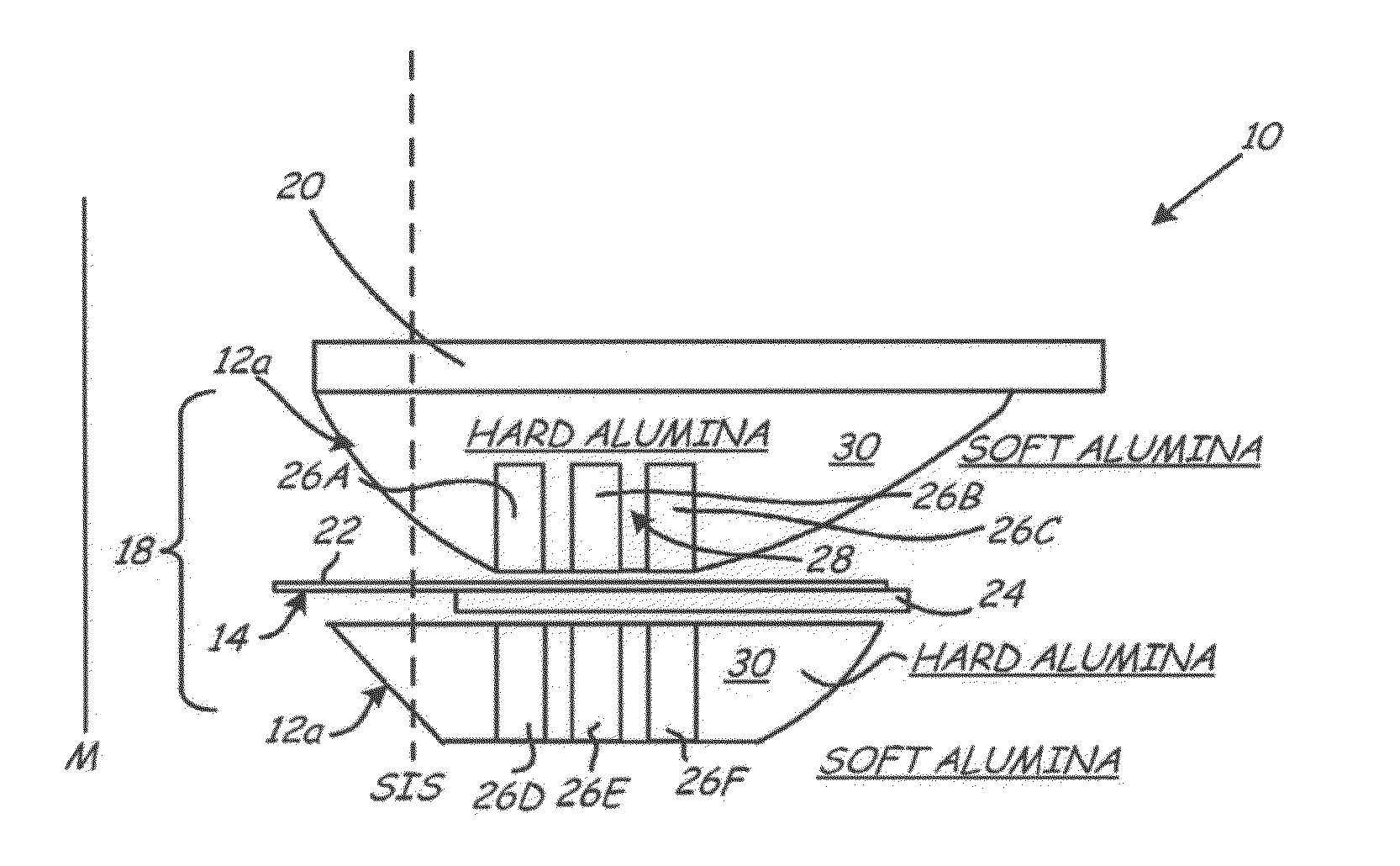
[0030]FIGS. 2A and 2B are sectional views of magnetic head 10 having contact enhancement feature 12A and writer 18 prior to lapping and after lapping, respectively. Writer 18 generally includes return pole 20, write pole 22, write pole tip 14 located at an end of write pole 22 at the SIS, yoke 24, write coil 26 (shown as write coil turns 26A, 26B, 26C, 26D, 26E, and 26F), and insulator 28. Although magnetic head 10 is shown having one return pole 20, writer 18 may have two return poles or no return pole without departing from the intended scope of the invention.
[0031]Return pole 20 and write pole 22 extend from the SIS and are connected to each other distal from the SIS. Yoke 24 is formed on write pole 22 but does not extend the full length of write pole 22. Insulator 28 separates return pole 20, write pole 22, and write coil 26 from each other. Return pole 20 and yoke 24 are formed from metallic ferromagnetic materials. Preferably, each of these components is formed from an alloy c...
second embodiment
[0037]Contact enhancement feature 12B of the second embodiment can be made of the same material as write coil 26, such as copper. However, using copper at the SIS presents the risk of corrosion or undesirable topography, which may make copper unsuitable for some applications. If copper is not a suitable choice for contact enhancement feature 12B, then silver, which has a higher resistance to corrosion, may be used. Silver is also a suitable candidate for use in forming write coil 26 because it can be readily plated and has very low electrical resistance. In addition, a designer willing to use additional photolithographic steps can also form contact enhancement feature 12B from NiCu.
[0038]As shown in FIGS. 3A and 3B, if contact enhancement feature 12B formed from write coil front shield 32 does not have a sufficient surface area to create a head-media contact area wide enough to protect write pole 22, supplementary contact enhancement feature 34 can be formed on top of write coil 26 ...
fourth embodiment
[0040]FIGS. 5A, 5B, and 5C show contact enhancement feature 12D prior to lapping, during lapping, and after lapping, respectively. Contact enhancement feature 12D is formed around write pole tip 14 such that write pole tip 14 is covered at the SIS by contact enhancement feature 12D. Magnetic head 10 is then heated such that write pole tip 14 and other elements surrounding write pole tip 14 are thermally protruded at the SIS. By heating the area around write pole tip 14 prior to lapping, it is more likely that write pole tip 14 is proximate the SIS to form at least a portion of the head-media contact surface. Contact enhancement feature 12D and write pole tip 14 are then lapped and burnished until the surfaces of write pole tip 14 and contact enhancement feature 12D are substantially planar and the resulting surface area is such that ̂PES or AE contact detection methods can be effectively used to detect contact between contact enhancement feature 12D and media M. In one embodiment, c...
PUM
| Property | Measurement | Unit |
|---|---|---|
| surface area | aaaaa | aaaaa |
| height | aaaaa | aaaaa |
| height | aaaaa | aaaaa |
Abstract
Description
Claims
Application Information
 - R&D
- Intellectual Property
- Life Sciences
- Materials
- Tech Scout
- Unparalleled Data Quality
- Higher Quality Content
- 60% Fewer Hallucinations
Browse by: Latest US Patents, China's latest patents, Technical Efficacy Thesaurus, Application Domain, Technology Topic, Popular Technical Reports.
© 2025 PatSnap. All rights reserved.Legal|Privacy policy|Modern Slavery Act Transparency Statement|Sitemap|About US| Contact US: help@patsnap.com