Phase interpolation circuit
a phase interpolation circuit and phase interpolation technology, applied in pulse manipulation, pulse technique, instruments, etc., can solve the problems of limited operating range and availability of low-voltage operations
- Summary
- Abstract
- Description
- Claims
- Application Information
AI Technical Summary
Benefits of technology
Problems solved by technology
Method used
Image

Examples
Embodiment Construction
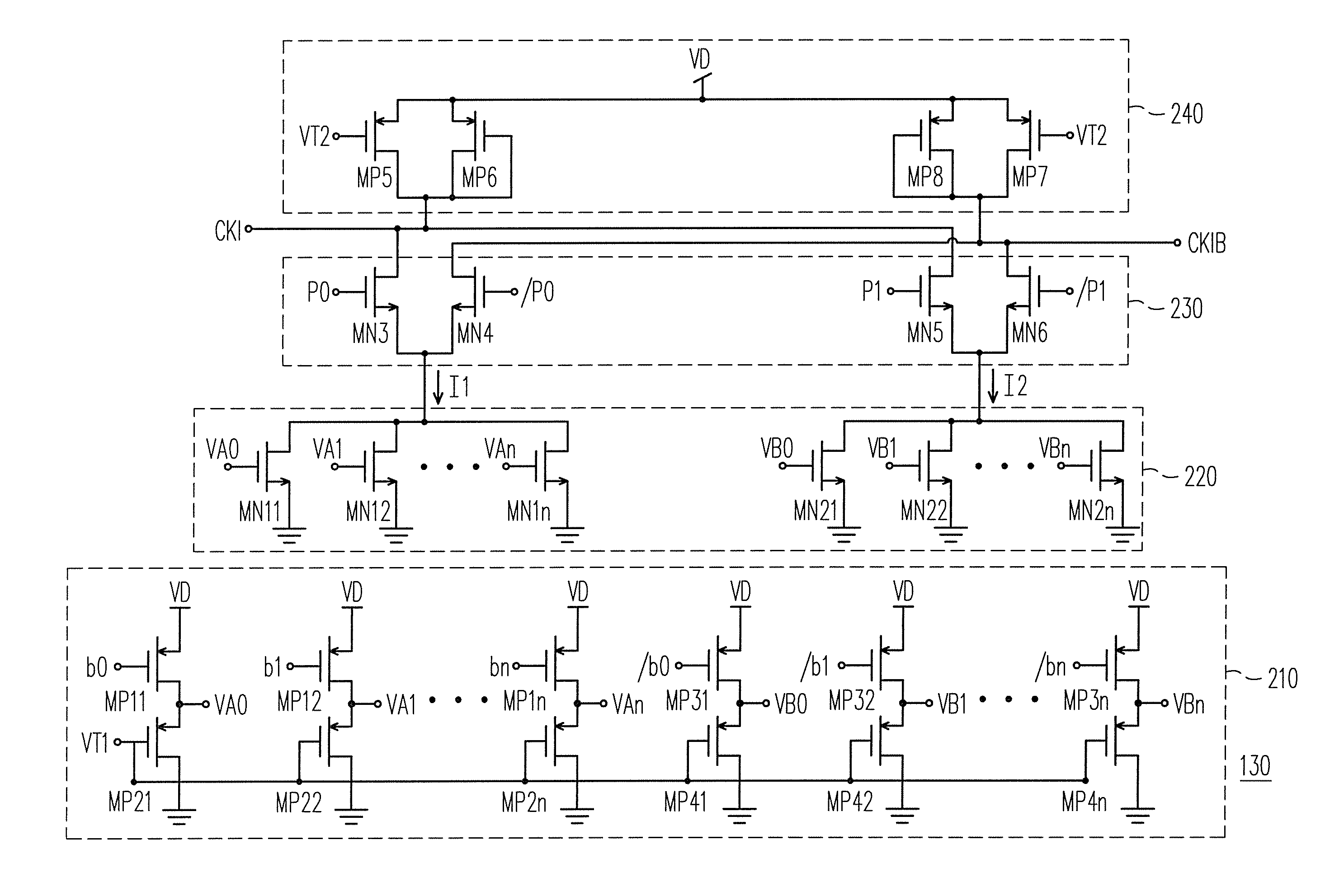
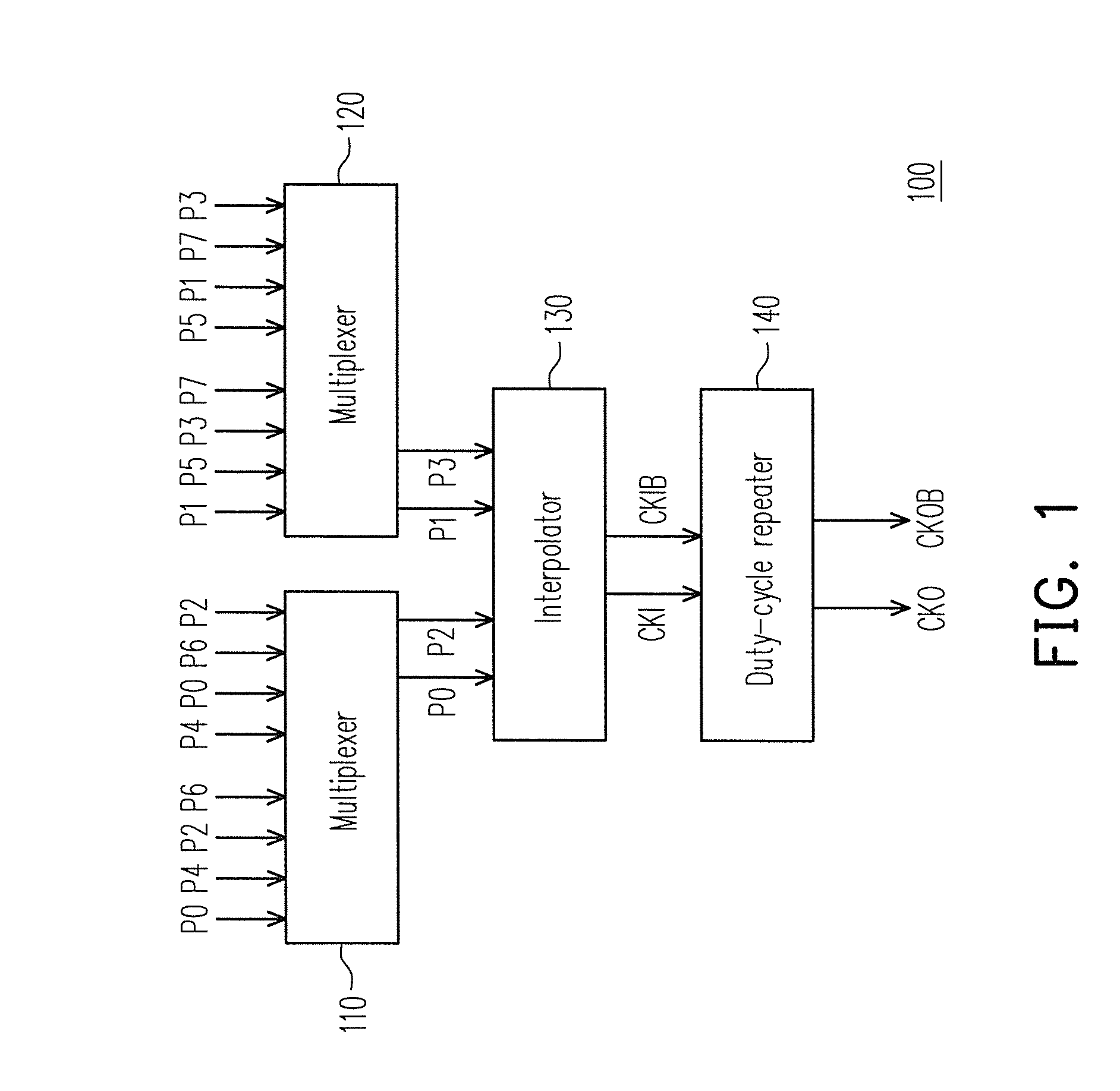
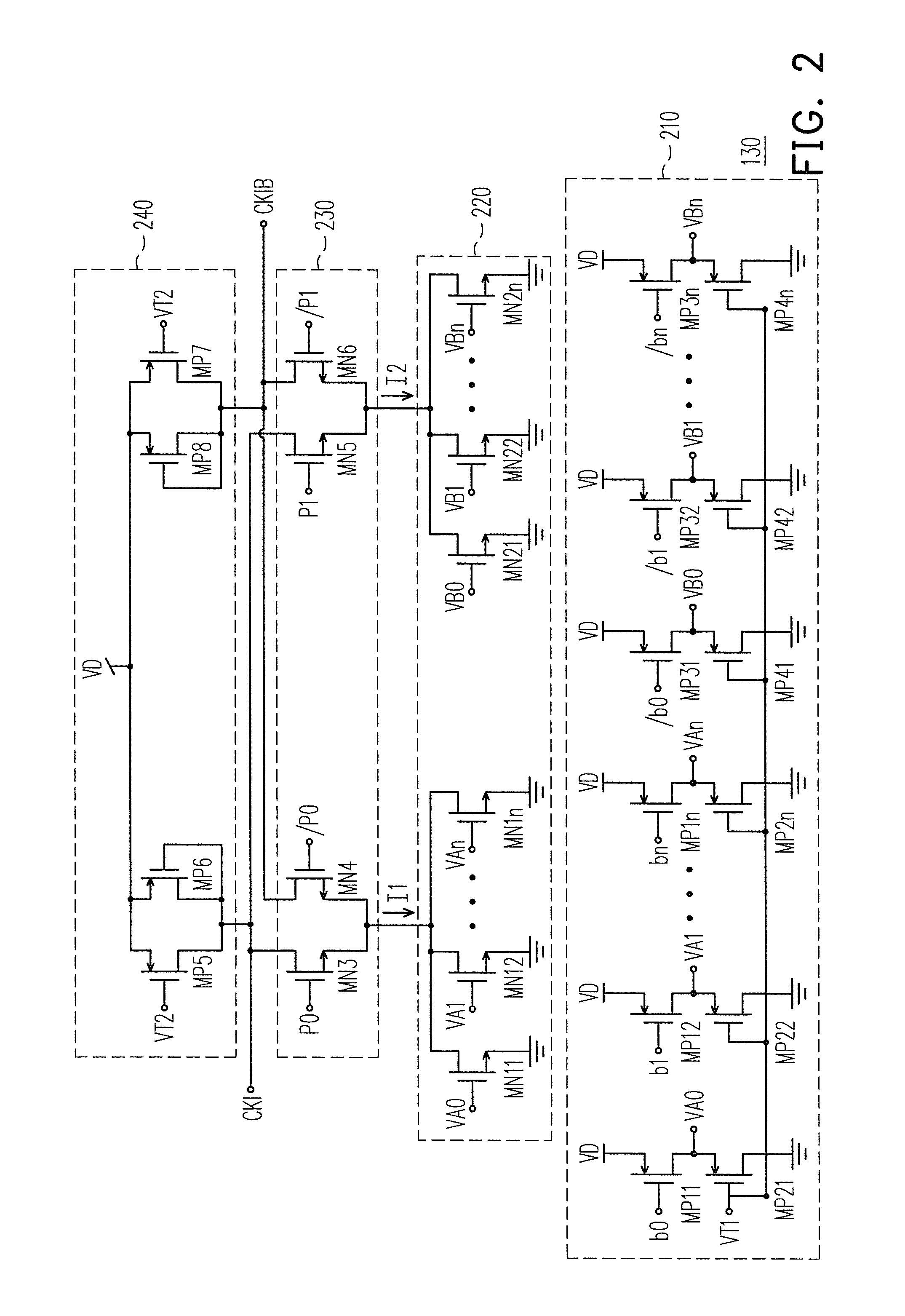
[0019]FIG. 1 is a block schematic diagram of a phase interpolation circuit according to an embodiment of the invention. Referring to FIG. 1, the phase interpolation circuit 100 includes a multiplexer 110, a multiplexer 120, an interpolator 130 and a duty-cycle repeater 140. The phase interpolation circuit 100 can be used in a clock and data recovery circuit, especially in a clock and data recovery circuit of a high-speed transmission interface module (for example, a universal serial bus (USB) 3.0 interface module).
[0020]Referring to FIG. 1, the multiplexer 110 and the multiplexer 120 respectively receive a plurality of phase signals. For example, in an exemplary embodiment, by equally dividing 360 degrees into 8 parts, 8 phase signals P0-P7, i.e. 0°, 45°, 90°, 135°, . . . , 315° are obtained. The 8 phase signals P0-P7 respectively have a phase difference of 45°. Moreover, the phase signals P0, P2, P4 and P6 are respectively an even multiple of the basic phase of 45°, so that the pha...
PUM
 Abstract
Description
Claims
Application Information
 - R&D
- Intellectual Property
- Life Sciences
- Materials
- Tech Scout
- Unparalleled Data Quality
- Higher Quality Content
- 60% Fewer Hallucinations
Browse by: Latest US Patents, China's latest patents, Technical Efficacy Thesaurus, Application Domain, Technology Topic, Popular Technical Reports.
© 2025 PatSnap. All rights reserved.Legal|Privacy policy|Modern Slavery Act Transparency Statement|Sitemap|About US| Contact US: help@patsnap.com