Supercharge Your Innovation With Domain-Expert AI Agents!

Overcurrent Detection Circuit and Overcurrent Detection Method

a detection circuit and overcurrent technology, applied in the direction of power conversion systems, parameter calibration/setting, electrical equipment, etc., can solve the problems of lowering the power efficiency of the power ic, affecting the stability of reference signals, and unable to accurately respond to overcurrent in the power system

Active Publication Date: 2013-06-27
ANPEC ELECTRONICS CORPORATION
View PDF2 Cites 9 Cited by
  • Summary
  • Abstract
  • Description
  • Claims
  • Application Information

AI Technical Summary

Benefits of technology

The present invention provides an overcurrent detection circuit and method for a DC-to-DC power converter. The circuit includes a dynamic reference unit, a load current measurement unit, and a first comparator. The dynamic reference unit generates a dynamic reference signal, and the load current measurement unit measures the current of the DC-to-DC power converter and outputs a measurement signal. The first comparator compares the measurement signal with the dynamic reference signal and outputs an overcurrent protection signal to activate the overcurrent protection device when the measurement signal is greater than the dynamic reference signal. The method thereof includes generating a measurement signal and a dynamic reference signal, and outputting an overcurrent protection signal to activate the overcurrent protection device based on the measurement signal and the dynamic reference signal. The technical effects of the invention are to provide a reliable overcurrent detection circuit and method that can prevent damage to the DC-to-DC power converter caused by overcurrent events.

Problems solved by technology

However, the stable reference signal may not accurately respond to an occurrence of overcurrent in the power system.
If during a period of low temperature and high voltage, the overcurrent detection circuit may activate the overcurrent protection circuit to drain the overcurrent earlier than the load current reaching the CLL, which may lower a power efficiency of the power IC.
If in the high temperature and the low voltage situation, the overcurrent detection circuit may activate the overcurrent protection circuit after the load current has reached the CLL, which may lead to the overcurrent protection circuit not draining the overcurrent in time, and risking damage to the power system or the load.
As can be seen, the CLL is deeply influenced by the temperature and the system voltage, which may lead to the stable reference signal not accurately responding to an occurrence of overcurrent in the power system.

Method used


Image

  • Overcurrent Detection Circuit and Overcurrent Detection Method
  • Overcurrent Detection Circuit and Overcurrent Detection Method
  • Overcurrent Detection Circuit and Overcurrent Detection Method

Examples


Embodiment Construction

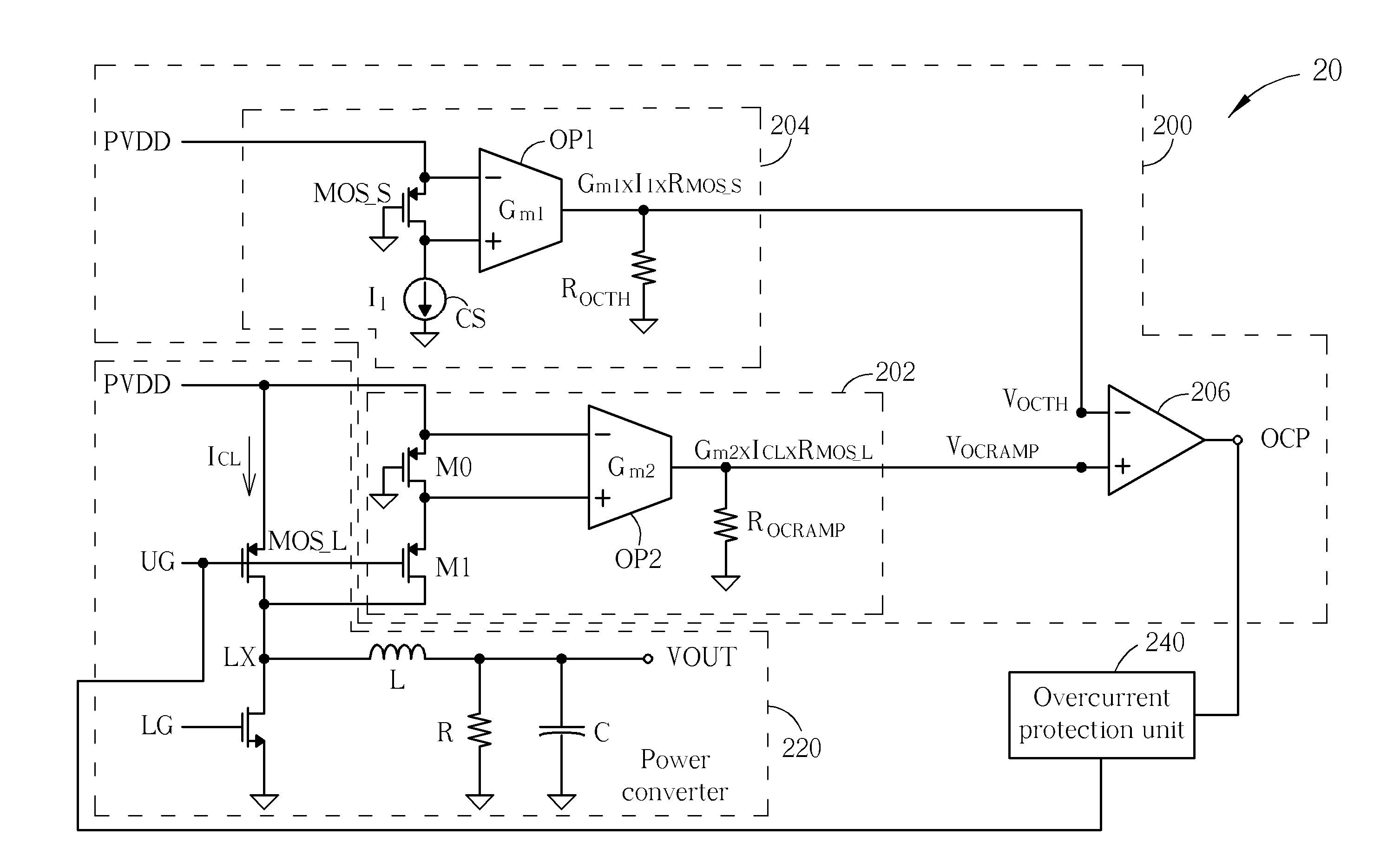
[0017]Please refer to FIG. 2, which is a schematic diagram of a power system 20 according to an embodiment of the present invention. The power system 20 includes an overcurrent detection circuit 200, a power converter 220 and an overcurrent protection unit 240. The overcurrent detection circuit 200 includes a measurement unit 202, a reference unit 204 and a comparator 206. The measurement unit 202 is used for detecting a load current ICL of the power converter 220 to generate a measurement signal VOCRAMP. The reference unit 204 is used for generating a reference signal VOCTH. A positive input terminal and a negative input terminal of the comparator 206 are respectively coupled to the measurement unit 202 and the reference unit 204 to output an overcurrent protection signal OCP to the overcurrent protection unit 240 when the measurement signal VOCRAMP is greater than the reference signal VOCTH, so as to drain the load current ICL of the power converter 220, which prevents the overcur...


PUM


Abstract

An overcurrent detection circuit for a DC-to-DC power converter is disclosed. The overcurrent detection circuit includes a dynamic reference unit for outputting a dynamic reference signal, a load current measurement unit for measuring a load current of the DC-to-DC power converter to output a measurement signal, and a first comparator including a positive input terminal coupled to the load current measurement unit, a negative input terminal coupled to the dynamic reference unit and an output terminal coupled to an overcurrent protection device for outputting an overcurrent protection signal to activate the overcurrent protection device when the measurement signal is greater than the dynamic reference signal.

Description

BACKGROUND OF THE INVENTION[0001]1. Field of the Invention[0002]The present invention relates to an overcurrent detection circuit and overcurrent detection method, and more particularly, to an overcurrent detection circuit and overcurrent detection method adjusting current limit level when the temperature and a system voltage vary.[0003]2. Description of the Prior Art[0004]A traditional overcurrent detection circuit measures a load current outputted by a power converter, and transfers the load current to an overcurrent signal to determine whether the load current is greater than a reference signal to activate an overcurrent protection circuit, so as to protect a power system from excess current damaging the power converter or the load. In general, the reference signal is commonly to be a stable reference signal, which has a zero temperature coefficient or has an isolated power source, in other words, the reference signal has a constant value no matter the temperature or a system vol...

Claims


Application Information

Patent Timeline
Patent Type & Authority Applications(United States)
IPC IPC(8): H02H3/087
CPCH02H3/087H02M1/32H02H9/025H02H3/006H02M2001/0009H02M1/0009
Inventor CHANG, HSIANG-CHUNGHSU, HUNG-TA
Owner ANPEC ELECTRONICS CORPORATION
Features
  • R&D
  • Intellectual Property
  • Life Sciences
  • Materials
  • Tech Scout
  • Unparalleled Data Quality
  • Higher Quality Content
  • 60% Fewer Hallucinations
Learn More