Supercharge Your Innovation With Domain-Expert AI Agents!

Scanning device, apparatus and method for image processing

a scanning device and image processing technology, applied in the field of scanning devices, imagescanners, apparatus and methods for image processing, can solve the problems of user inconvenience and increase of costs

Active Publication Date: 2013-10-10
PFU LTD
View PDF2 Cites 1 Cited by
  • Summary
  • Abstract
  • Description
  • Claims
  • Application Information

AI Technical Summary

Benefits of technology

This configuration reduces the overall size of the scanning device, eliminates unnecessary spaces, and simplifies the calibration process by minimizing the depth required for sensor arrangement and eliminating the need for manual calibration data storage.

Problems solved by technology

Therefore, calibration data used for shading correction is stored in a memory (not shown) of the scanning device, which causes increase of costs.
In addition, the calibration operation must be performed manually such that a sheet of paper is scanned and the image data is processed, which causes inconvenience to a user.

Method used


Image

  • Scanning device, apparatus and method for image processing
  • Scanning device, apparatus and method for image processing
  • Scanning device, apparatus and method for image processing

Examples


Embodiment Construction

[0030]Exemplary embodiments of the present invention are explained in detail below with reference to the accompanying drawings.

[0031]The same reference numerals are used for components that have the same function as those in the above conventional scanning device, and detailed descriptions of such components are omitted.

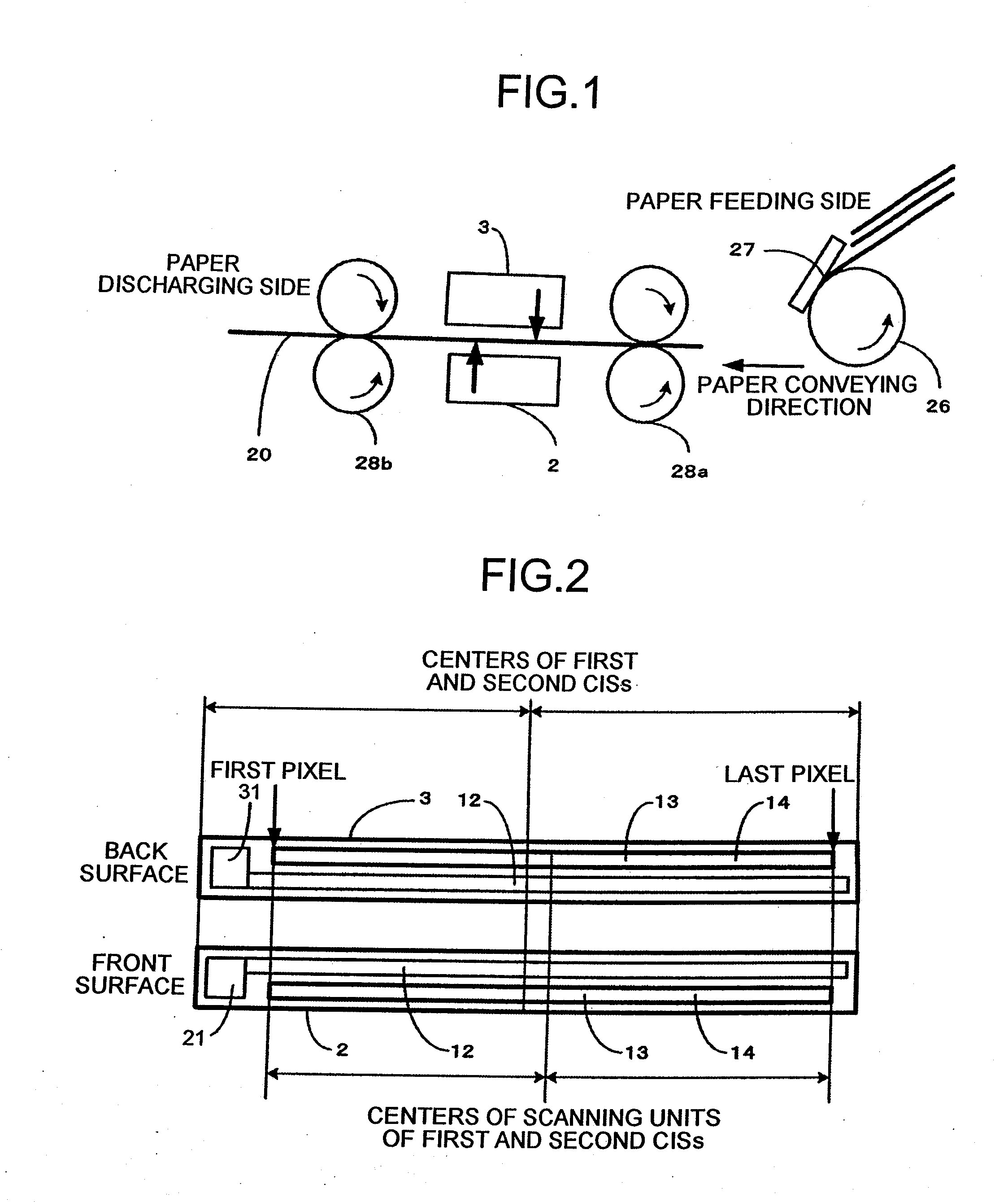
[0032]FIG. 1 is a schematic diagram of a scanning device according to an embodiment of the present invention. The first CIS 2 is arranged to face the front surface of the printed paper 20, and the second CIS 3 is arranged to face the back surface of the printed paper 20. The first CIS 2 and the second CIS 3 concurrently scan the front and the back surfaces thereby obtaining images of the printed paper 20. The first CIS 2 scans the front surface in the forward direction with respect to the front surface, and the second CIS 3 scans the back surface in a backward direction, which is a direction opposite to the forward direction, with respect to the back surface. In othe...


PUM


Abstract

A scanning device includes a first scanning unit, a second scanning unit, and a light source corresponding to each of the first scanning unit and the second scanning unit. The light sources are arranged on the same side of the first and second scanning units with respect to the main scanning direction.

Description

BACKGROUND OF THE INVENTION[0001]1. Field of the Invention[0002]The present invention relates to a technology for scanning the front and the back surfaces of a paper.[0003]2. Description of the Related Art[0004]Various approaches have been taken to reduce the size of a scanning device. For example, use of a contact image sensor (CIS), use a CIS having fewer light emitting diodes (LEDs), etc. helps to reduce the size of a scanning device.[0005]FIG. 7A is a schematic diagram of a conventional CIS 1. FIG. 7B is a side view of the conventional CIS 1 taken along a line A-A shown in FIG. 7A. FIG. 7C is a schematic diagram for explaining scanning operation performed by the conventional CIS 1.[0006]The CIS 1 includes a light source 11 arranged at a first end in a main scanning direction. Although not shown, the light source 11 includes three-color LEDs, i.e., a red LED that emits a red light beam, a green LED that emits a green light beam, and a blue LED that emits a blue light beam. When t...

Claims


Application Information

Patent Timeline
Patent Type & Authority Applications(United States)
IPC IPC(8): H04N1/46
CPCH04N1/00525H04N1/12H04N1/193H04N1/46H04N1/2032H04N2201/0081H04N1/203
Inventor KUBO, SATOSHINAKASHIMA, YUSUKEKITAGAWA, YASUHIKO
Owner PFU LTD
Features
  • R&D
  • Intellectual Property
  • Life Sciences
  • Materials
  • Tech Scout
  • Unparalleled Data Quality
  • Higher Quality Content
  • 60% Fewer Hallucinations
Learn More