Apparatus and method for controlling coexistence interference within device in wireless communication system

Inactive Publication Date: 2013-10-24
PANTECH CO LTD
View PDF3 Cites 25 Cited by
  • Summary
  • Abstract
  • Description
  • Claims
  • Application Information

AI Technical Summary

Benefits of technology

[0020]According to the present invention, in-device coexistence interference can be detected with ease; the process of resolving coexistence interference within the device can be simplified; and implementation thereof can be easily achieved and reverse c

Problems solved by technology

Although it is essential to increase bandwidth to meet the demand for high transmission capacity, supporting high bandwidth even when quality of service required is low may incur large power consumption.
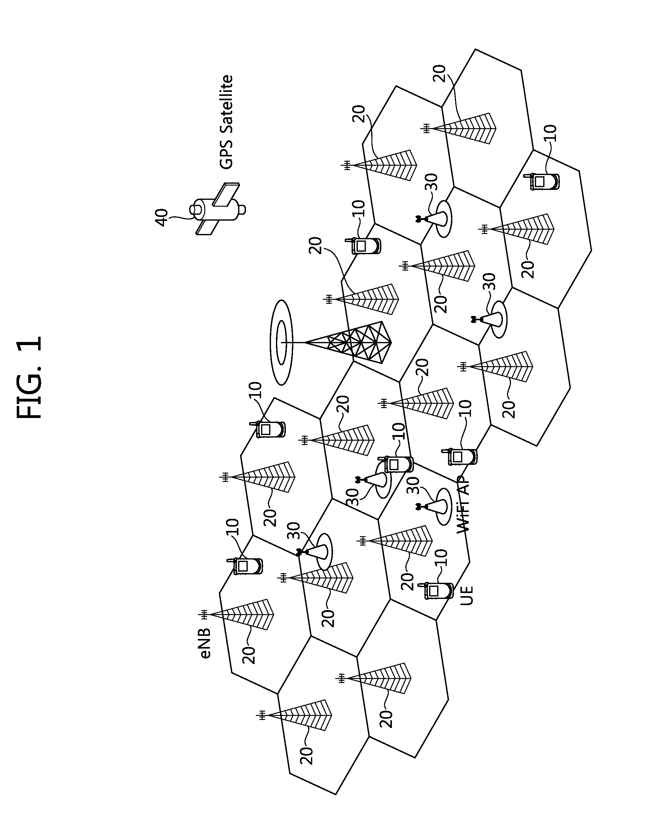
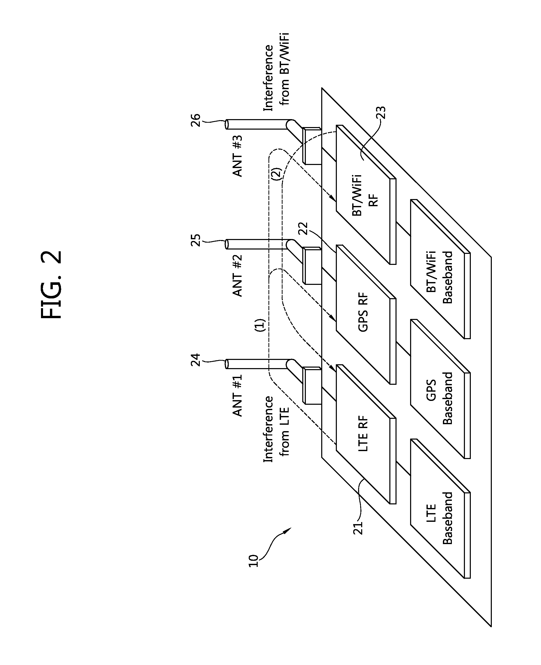
However, in the case where single UE performs communication simultaneously through frequency bands of a plurality of network systems, in-device coexistence interference may occur.
In-device coexistence interference refers to such kind of interference that causes interfer

Method used


Image

  • Apparatus and method for controlling coexistence interference within device in wireless communication system
  • Apparatus and method for controlling coexistence interference within device in wireless communication system
  • Apparatus and method for controlling coexistence interference within device in wireless communication system

Examples


Embodiment Construction

[0036]In what follows, part of the embodiments of the present document will be described in detail with reference to exemplary drawings. In assigning reference symbols to constituting elements in each drawing, it should be noted that the same symbols are assigned to the same constituting elements as possibly as can be even though they appear in different drawings. Also, in describing embodiments of the present invention, if it is determined that detailed description of a related structure or function known for those in the art obscures the technical principles of the present invention, the corresponding description will be omitted.

[0037]Also, in describing constituting elements of the present document, terms such as first, second, A, B, (a), (b), and the like can be used. Those terms are introduced only for the purpose of distinguishing a constituting element from the others; therefore, inherent characteristics, order, or sequence of the corresponding constituting element is not lim...


PUM


Abstract

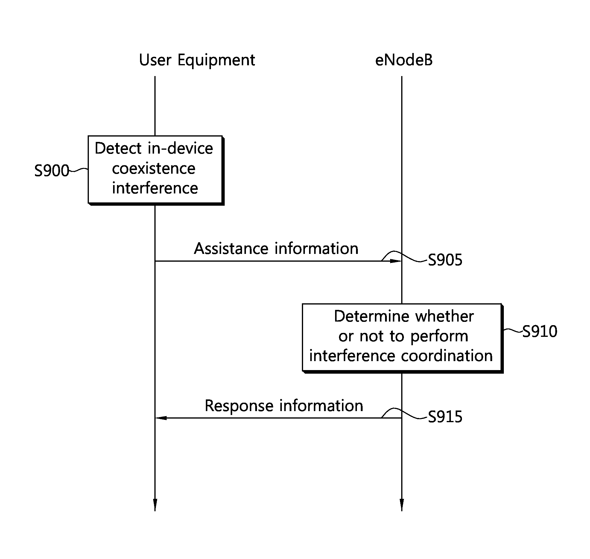
The present specification discloses the following steps: detecting a transmission from a first frequency band in a first network system causing interference on a reception in a second frequency band in a second network system; transmitting to a base station support information for supporting control of the interference that is detected; and receiving from the base station reply information for accepting or denying control of the interference that is detected, as a reply to the support information. The coexistence interference within the device can be detected, the resolving process thereof can be simplified and achievable, and reverse compatibility with other existing processes can be maintained.

Description

CROSS-REFERENCE TO RELATED APPLICATIONS[0001]This application is the National Stage Entry of International Application PCT / KR2012 / 000145, filed on Jan. 9, 2012, and claims priority from and the benefit of Korean Patent Application No. 10-2011-0001741, filed on Jan. 7, 2011, Korean Application No. 10-2011-0012058, filed on Feb. 10, 2011, and Korean Application No. 10-2011-0032873, filed on Apr. 8, 2011, all of which are incorporated herein by reference for all purposes as if fully set forth herein.BACKGROUND[0002]1. Field[0003]The present invention relates to wireless communication and, more particularly, an apparatus and a method for coordinating in-device coexistence interference in a wireless communication system.[0004]2. Discussion of the Background[0005]A conventional wireless communication system uses a single frequency band for data transmission. For example, the second-generation wireless communication system uses bandwidth of 200 KHz to 1.25 MHz, whereas the third-generation...

Claims


Application Information

Patent Timeline
IPC IPC(8): H04W24/02
CPCH04W24/02H04W72/1215H04B17/11H04B17/345H04B15/00H04W36/20H04W88/02H04W88/08
Inventor AHN, JAE HYUNKWON, KI BUMJUNG, MYUNG CHEUL
Owner PANTECH CO LTD
Why Eureka
Try Eureka