Supercharge Your Innovation With Domain-Expert AI Agents!

Variable Speed Toggle Trigger

a toggle trigger and variable speed technology, applied in the direction of resistors, switches with two operating positions, adjustable resistors, etc., can solve the problem of somewhat expensive manufacturing

Active Publication Date: 2013-10-31
SNAP ON INC
View PDF2 Cites 2 Cited by
  • Summary
  • Abstract
  • Description
  • Claims
  • Application Information

AI Technical Summary

Benefits of technology

Enables users to reverse motor direction and apply variable power with a single trigger mechanism, simplifying design and reducing component costs while maintaining efficient motor control.

Problems solved by technology

This design requires two separate triggers that are mechanically coupled together by a rotating toggle switch and are somewhat expensive to manufacture due to the requirement of two switches.

Method used


Image

  • Variable Speed Toggle Trigger
  • Variable Speed Toggle Trigger
  • Variable Speed Toggle Trigger

Examples


Embodiment Construction

[0018]While the present invention is susceptible of embodiments in many different forms, there is shown in the drawings and will be herein described in detail a preferred embodiment of the invention with the understanding that the present disclosure is to be considered as an exemplification of the principles of the invention and is not intended to limit the broad aspect of the invention to embodiments illustrated.

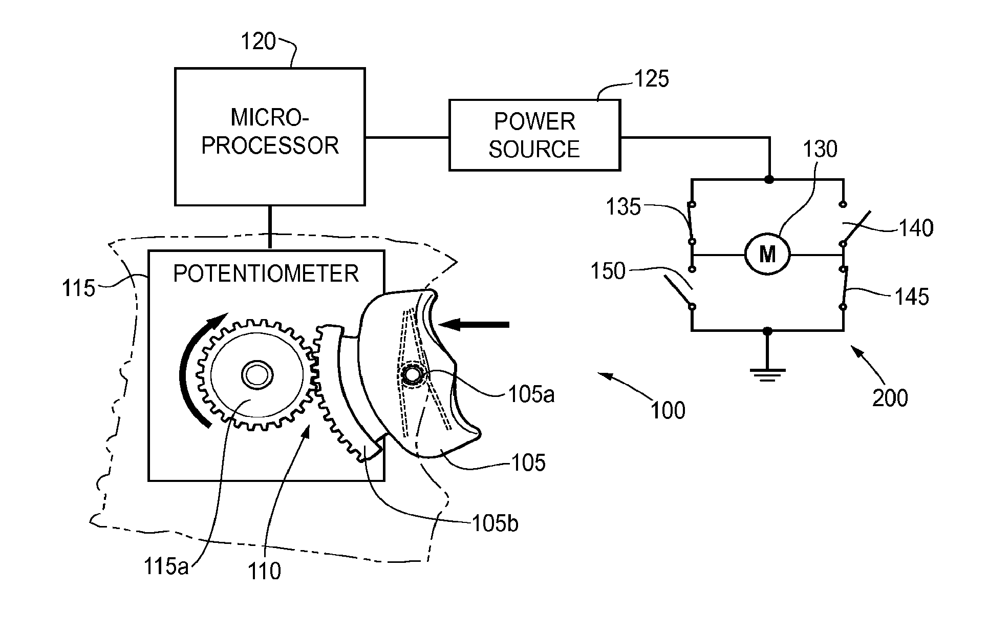
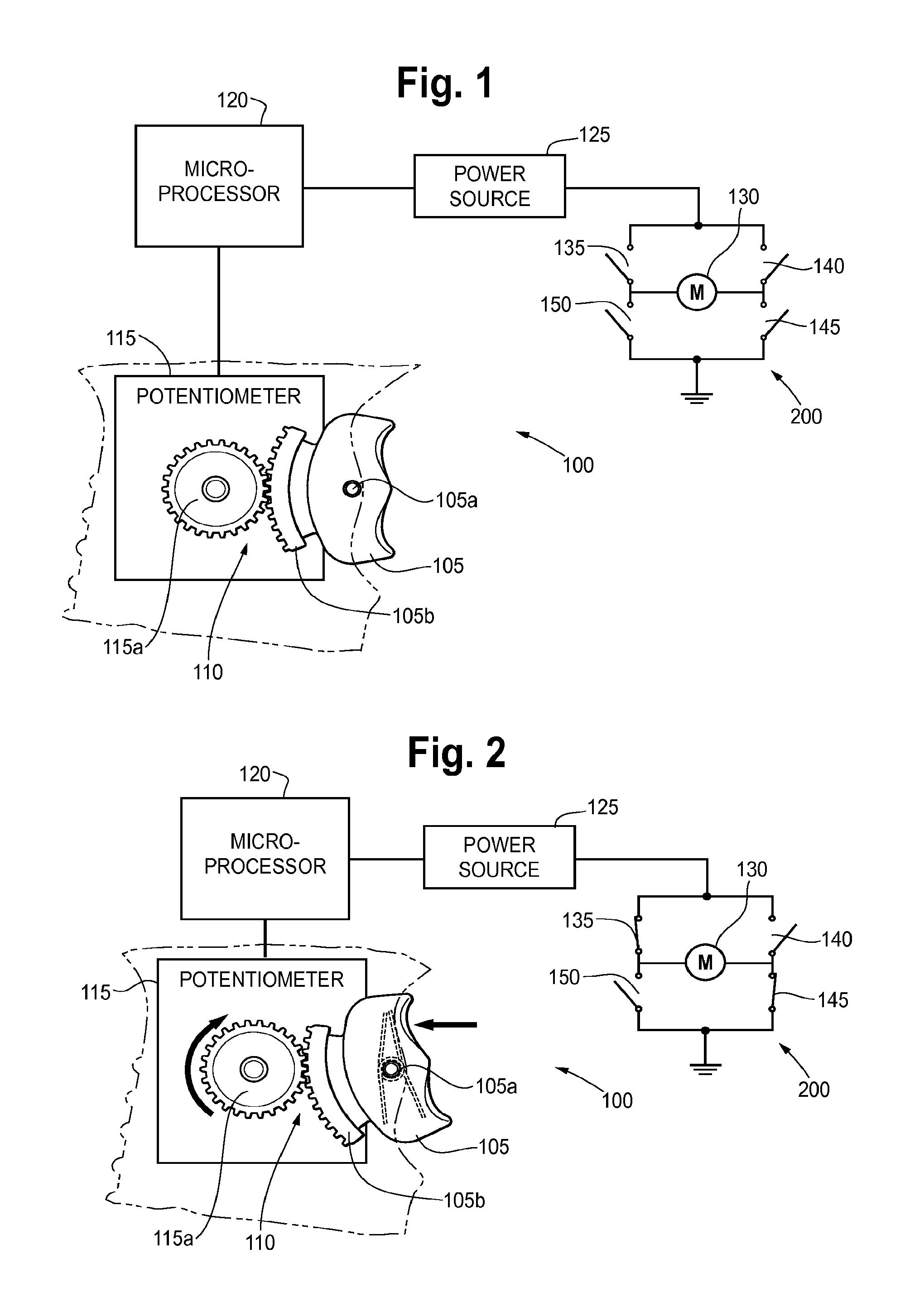
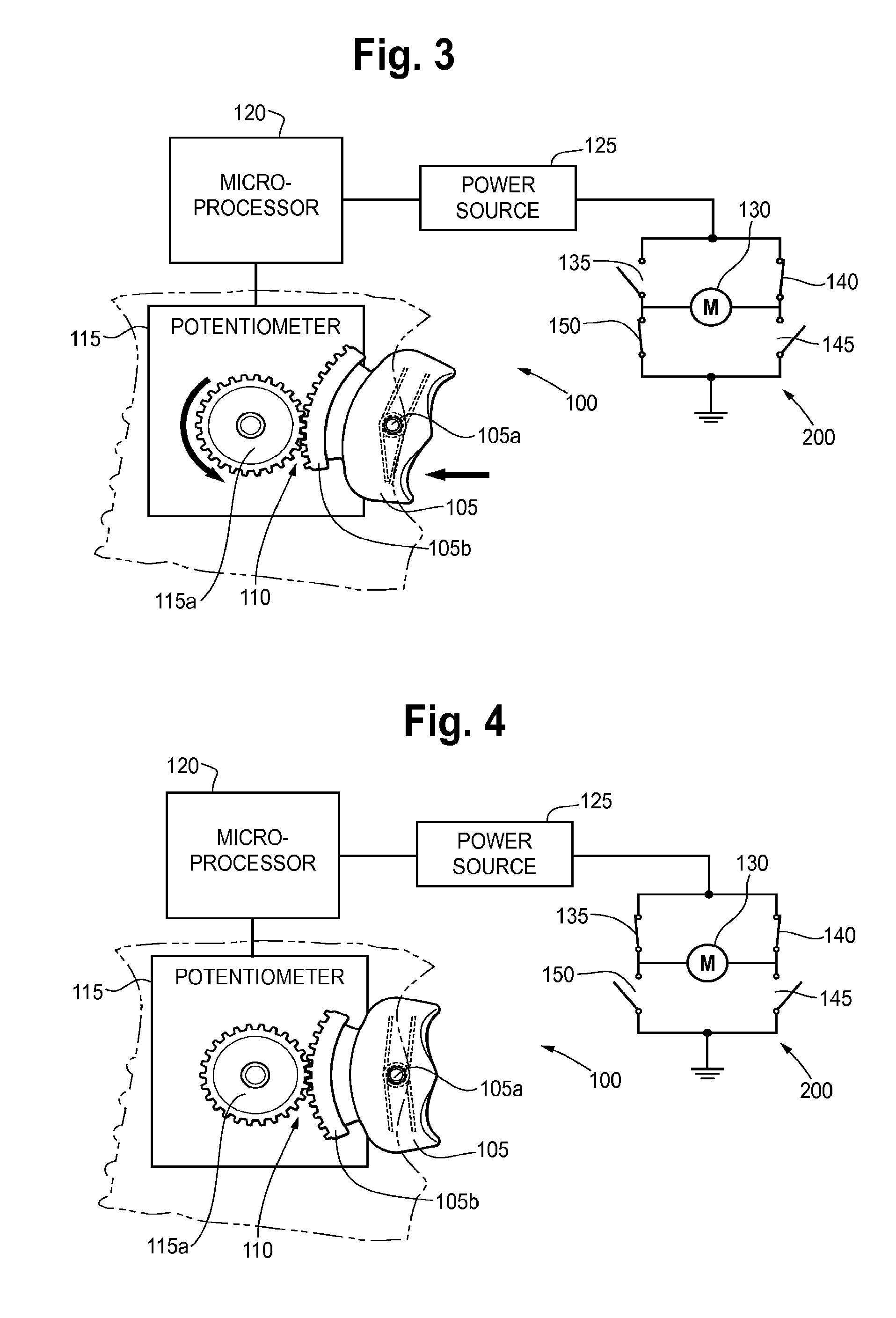
[0019]The present application is directed to a switch adapted for use with a motor, such as disposed in a power tool, such as, for example, a power drill. In an embodiment, the variable speed toggle switch allows a user to choose a rotational direction of a motor and supply variable amounts of power to the motor. The trigger includes a gear segment that meshingly engages a gear on a potentiometer to electrically communicate the actuation direction and actuation amount of the trigger to a microprocessor. The microprocessor can then signal to an H-bridge, or to a series of tr...


PUM


Abstract

A variable speed toggle switch that allows a user to reverse a rotational direction of a motor and supply variable amounts of power to a motor, such as in a power tool, for example, a power drill. A trigger can include a gear segment that meshingly engages a gear on a potentiometer to electrically communicate the actuation direction and actuation amount of the trigger to a microprocessor. The microprocessor can then signal to an H-bridge, or to a series of transistors, the actuation direction and actuation amount of the trigger. A motor or other device can be powered by a power source in an amount corresponding to the actuation amount, and in a direction corresponding to the actuation direction of the trigger.

Description

RELATED APPLICATIONS[0001]The present application is a continuation of U.S. Ser. No. 13 / 250,284 filed Sep. 30, 2011, the filing priority of which is claimed and the entire disclosure of which is hereby incorporated by reference.FIELD OF THE INVENTION[0002]The present application relates generally to a trigger for a power tool. More particularly, the present application relates to a variable speed toggle trigger that allows a user to reverse the rotational output of a motor and supply variable amounts of power to the motor.BACKGROUND OF THE INVENTION[0003]Many conventional power tools include triggers or switches that facilitate the transfer of power from a power source to motor of the tool. For example, power drills have variable speed triggers that transfer a small amount of power to the drill bit when the trigger is depressed only slightly, but transfer a greater amount of power when fully depressed, thus causing the motor output to increase. These conventional tools may further i...

Claims


Application Information

Patent Timeline
Patent Type & Authority Applications(United States)
IPC IPC(8): H01C10/50
CPCH01C10/50H01H9/061H01H21/24H01H23/24
Inventor PUSATERI, DANIELHAPP, KENNETH C.BREHM, JAMES R.
Owner SNAP ON INC
Features
  • R&D
  • Intellectual Property
  • Life Sciences
  • Materials
  • Tech Scout
  • Unparalleled Data Quality
  • Higher Quality Content
  • 60% Fewer Hallucinations
Learn More