Supercharge Your Innovation With Domain-Expert AI Agents!

Lens system, optical apparatus and manufacturing method

a technology of lens system and optical apparatus, applied in the field of lenses system, can solve the problems of affecting the overall the complexity of the focusing mechanism, and the large size of the support mechanism and the driver mechanism of the focusing lens group, and achieve the effect of simplifying the focusing mechanism and reducing the total length of the lens system

Inactive Publication Date: 2013-12-26
NIKON CORP
View PDF3 Cites 2 Cited by
  • Summary
  • Abstract
  • Description
  • Claims
  • Application Information

AI Technical Summary

Benefits of technology

The present invention provides a lens system, optical apparatus, and manufacturing method that can simultaneously achieve a decrease in the overall length of the lens system and simplification of the focusing mechanism by appropriately setting the arrangement of the focusing lens group. Additionally, the invention can shift images with excellent image forming performance even if the shift lens group is shifted, and minimize the influence of decentering to prevent deterioration of performance. In the first aspect of the invention, it is preferable that the rear portion lens group of the first lens group has positive refractive power.

Problems solved by technology

However if focusing is attempted using the conventional front lens feed method, the support mechanism and driver mechanism of the focusing lens group tend to be large, since the large and heavy lens group that is disposed closest to the object is normally moved.
However in the case of the internal focusing method, the focusing mechanism tends to become complicated, since focusing cannot be performed on objects at a same photographic distance with a same feed amount throughout the entire zooming range from the wide angle end state to the telephoto end state.
However if a lens group which moves during zooming, is decentered for the purpose of vibration proofing as in the case of a conventional optical system, the optical performance may dramatically drop, which makes it impossible to obtain good images.

Method used


Image

  • Lens system, optical apparatus and manufacturing method
  • Lens system, optical apparatus and manufacturing method
  • Lens system, optical apparatus and manufacturing method

Examples


first embodiment

Examples of the First Embodiment Group

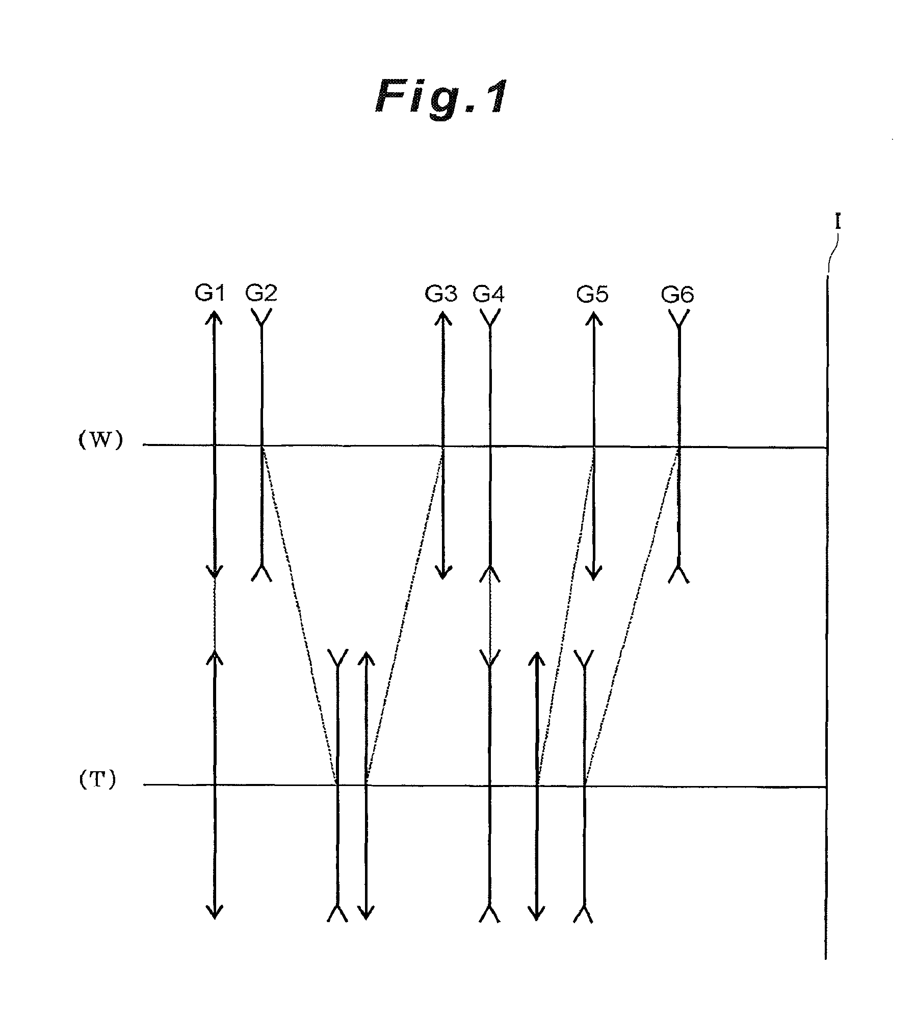
[0188]Each example (Example 1 to Example 5) in the first embodiment group will now be described with reference to the drawings. FIG. 1 is a diagram depicting the allocation of refractive power in the lens system and a shifting state of each lens group upon changing of the focal length state from the wide angle end state (W) to the telephoto end state (T) according to each example. As FIG. 1 shows, the lens system according to each example has, in order from the object, a first lens group G1 having positive refractive power, a second lens group G2 having negative refractive power, a third lens group G3 having positive refractive power, a fourth lens group G4 having negative refractive power, a fifth lens group G5 having positive refractive power, and a sixth lens group G6 having negative refractive power. And upon changing of the focal length state (that is, zooming) from the wide angle end state to the telephoto end state, the first lens group G...

example 1

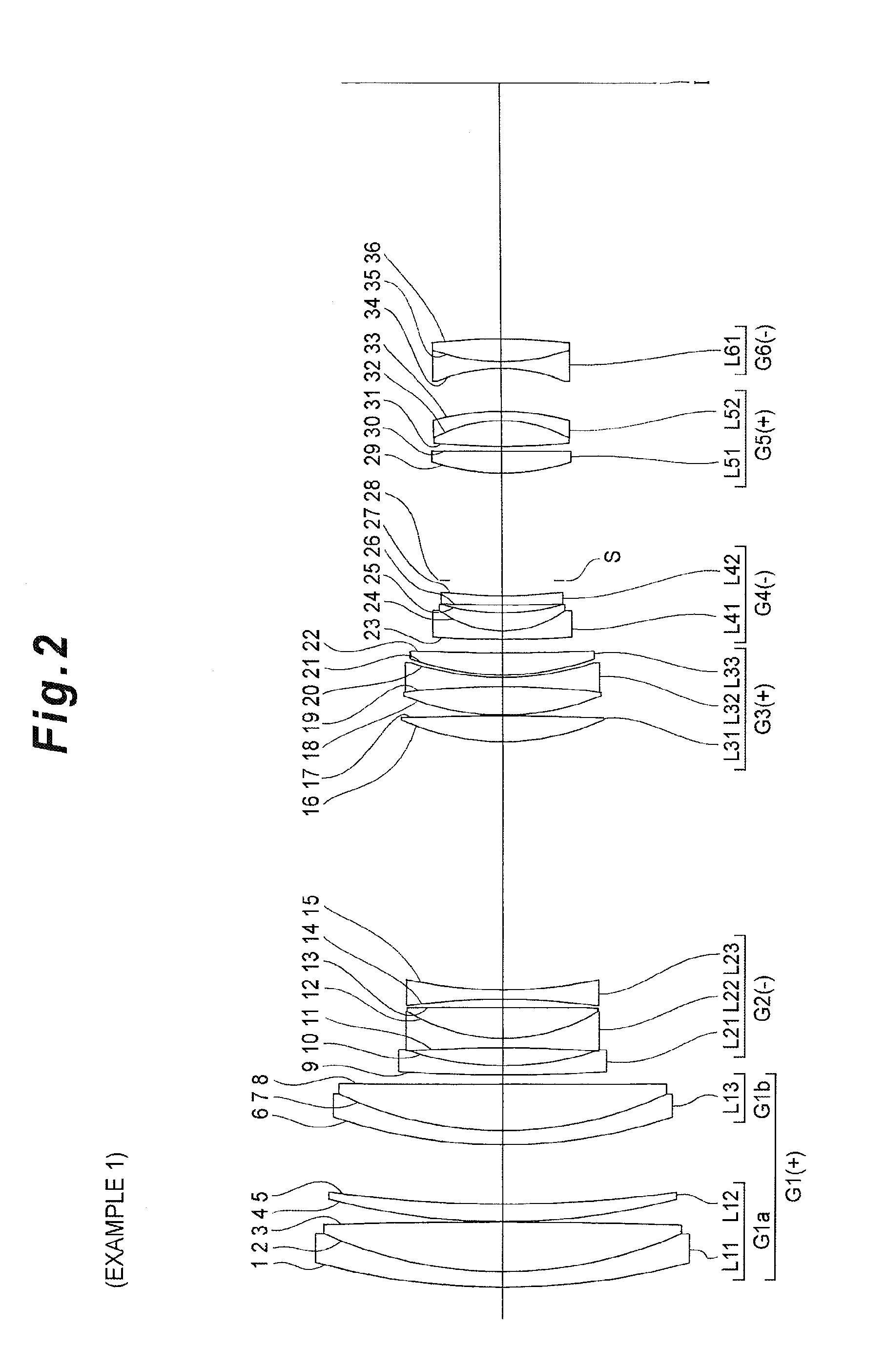
[0195]Example 1 will now be described with reference to FIG. 2 to FIG. 5 and Table 1 to Table 5. FIG. 2 is a diagram depicting a configuration of a lens system according to Example 1. As FIG. 2 shows, in the lens system according to Example 1, the first lens group G1 has, in order from the object, a front portion lens group G1a and a rear portion lens group G1b. The front portion lens group G1a has, in order from the object, a cemented positive lens L11 in which a negative meniscus lens having a convex surface facing the object and a biconvex lens are cemented, and a positive meniscus lens L12 having a convex surface facing the object. The rear portion lens group G1b has, in order from the object, a cemented positive lens L13 in which a negative meniscus lens having a convex surface facing the object and a positive meniscus lens having a convex surface facing the object are cemented.

[0196]The second lens group G2 has, in order from the object, a negative meniscus lens L21 having a c...

example 2

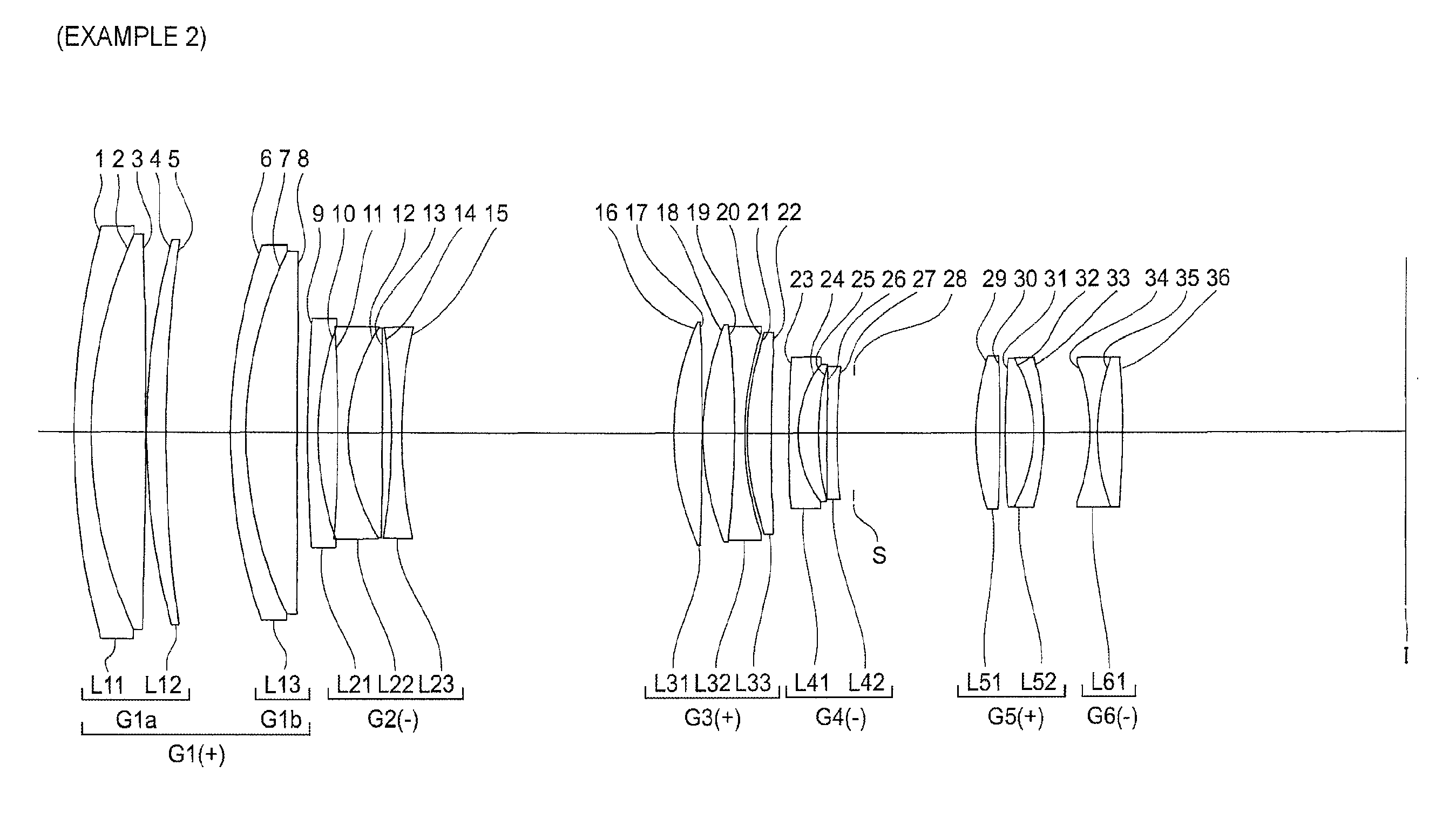
[0211]Example 2 will now be described with reference to FIG. 6 to FIG. 9 and Table 6 to Table 10. FIG. 6 is a diagram depicting a configuration of a lens system according to Example 2. As FIG. 6 shows, in the lens system according to Example 2, the first lens group G1 has, in order from the object, a front portion lens group G1a and a rear portion lens group G1b. The front portion lens group G1a has, in order from the object, a cemented positive lens L11 in which a negative meniscus lens having a convex surface facing the object and a biconvex lens are cemented, and a positive meniscus lens L12 having a convex surface facing the object. The rear portion lens group G1b has, in order from the object, a cemented positive lens L13 in which a negative meniscus lens having a convex surface facing the object and a positive meniscus lens having a convex surface facing the object are cemented.

[0212]The second lens group G2 has, in order from the object, a negative meniscus lens L21 having a ...


PUM


Abstract

A lens system having, in order from an object, at least a first lens group G1 having positive refractive power, and second to fourth lens groups G2 to G4, wherein the first lens group G1 includes a front portion lens group G1a, and a rear portion lens group G1b which is disposed to an image side of the front portion lens group G1a with an air distance therebetween, and performs focusing by shifting the rear portion lens group G1b in the optical axis direction, and the fourth lens group G4 includes, in order from the object, a negative lens and a positive lens (cemented negative lens L41), a negative lens L42, and an aperture stop S, and is fixed in the optical axis direction with respect to an image plane I upon zooming from a wide angle end state to a telephoto end state.

Description

INCORPORATION BY REFERENCE[0001]This invention claims the benefit of Japanese Patent Application Nos. 2009-127260, 2009-127261, 2009-127262 and 2009-127263 which are hereby incorporated by reference.TECHNICAL FIELD AND BACKGROUND[0002]The present invention relates to a lens system that is used for an optical apparatus such as a digital still camera.[0003]As a focusing method for a high zoom ratio optical system, a front lens feed method for feeding a lens group disposed closest to the object (e.g. see Japanese Laid-Open Patent Publication No. H11-258504) and an internal focusing method (e.g. see Japanese Laid-Open Patent Publication No. 2004-212612) have been known.[0004]However if focusing is attempted using the conventional front lens feed method, the support mechanism and driver mechanism of the focusing lens group tend to be large, since the large and heavy lens group that is disposed closest to the object is normally moved. The total length of the lens system also tends to incr...

Claims


Application Information

Patent Timeline
Patent Type & Authority Applications(United States)
IPC IPC(8): G02B15/14G02B27/64
CPCG02B15/14G02B27/646G02B15/173G02B15/1461Y10T29/49004Y10T29/49826G02B15/163G02B15/20
Inventor TAKE, TOSHINORI
Owner NIKON CORP
Features
  • R&D
  • Intellectual Property
  • Life Sciences
  • Materials
  • Tech Scout
  • Unparalleled Data Quality
  • Higher Quality Content
  • 60% Fewer Hallucinations
Learn More