
Efficient extended power headroom reporting for semi-persistent scheduling

Active Publication Date: 2014-01-23
PANASONIC INTELLECTUAL PROPERTY CORP OF AMERICA
View PDF1 Cites 62 Cited by
  • Summary
  • Abstract
  • Description
  • Claims
  • Application Information

AI Technical Summary

Benefits of technology

The invention provides a better way for a user equipment to send power headroom information to a base station, especially when using a persistently-allocated uplink resource. By transmitting the information in two parts - a basic and an extended power headroom report - no data delay is introduced. The transport block contains both data and the power headroom report, so the data does not have to be segmented and is not delayed. To avoid delay, an additional prioritization rule is suggested, which prioritizes any uplink data over the power headroom report for assignments that are persistently scheduled. This helps to ensure that essential data, like voice data, is not delayed.

Problems solved by technology

Consequently, the VoIP data cannot be transmitted in the same grant.
RLC segmentation of VoIP packets is disadvantageous since there is a strict delay requirement for VoIP services.
Another disadvantage of allocating a larger transport block size for VoIP applications, e.g. 392 bits, would be a reduced scheduling flexibility for retransmissions, since there are less 392 bit entries in transport block size table.
The definition of a new transport block size table for Rel-10, considering the extended power headroom reporting, is difficult, since the extended power headroom report is variable; thus, the transport block size table would not be optimized for all possible ePHR MAC control element sizes.
Furthermore a Rel-10 UE would need to support multiple transport block size tables in order to support basic (Rel-8 / 9 PHR MAC control element) power headroom reporting and extended power headroom reporting, which increases the complexity.

Method used


Image

  • Efficient extended power headroom reporting for semi-persistent scheduling
  • Efficient extended power headroom reporting for semi-persistent scheduling
  • Efficient extended power headroom reporting for semi-persistent scheduling

Examples


Embodiment Construction

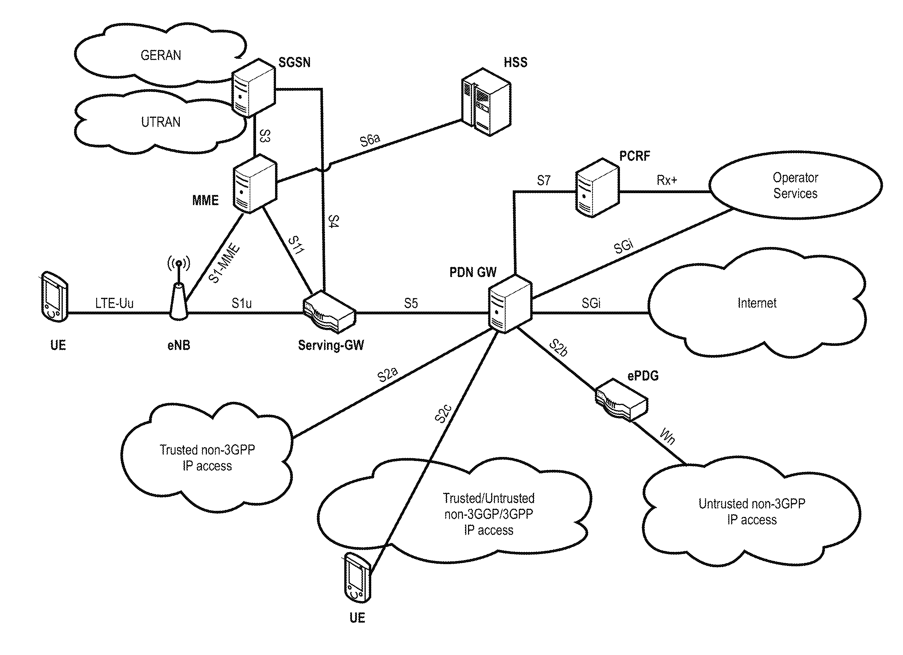
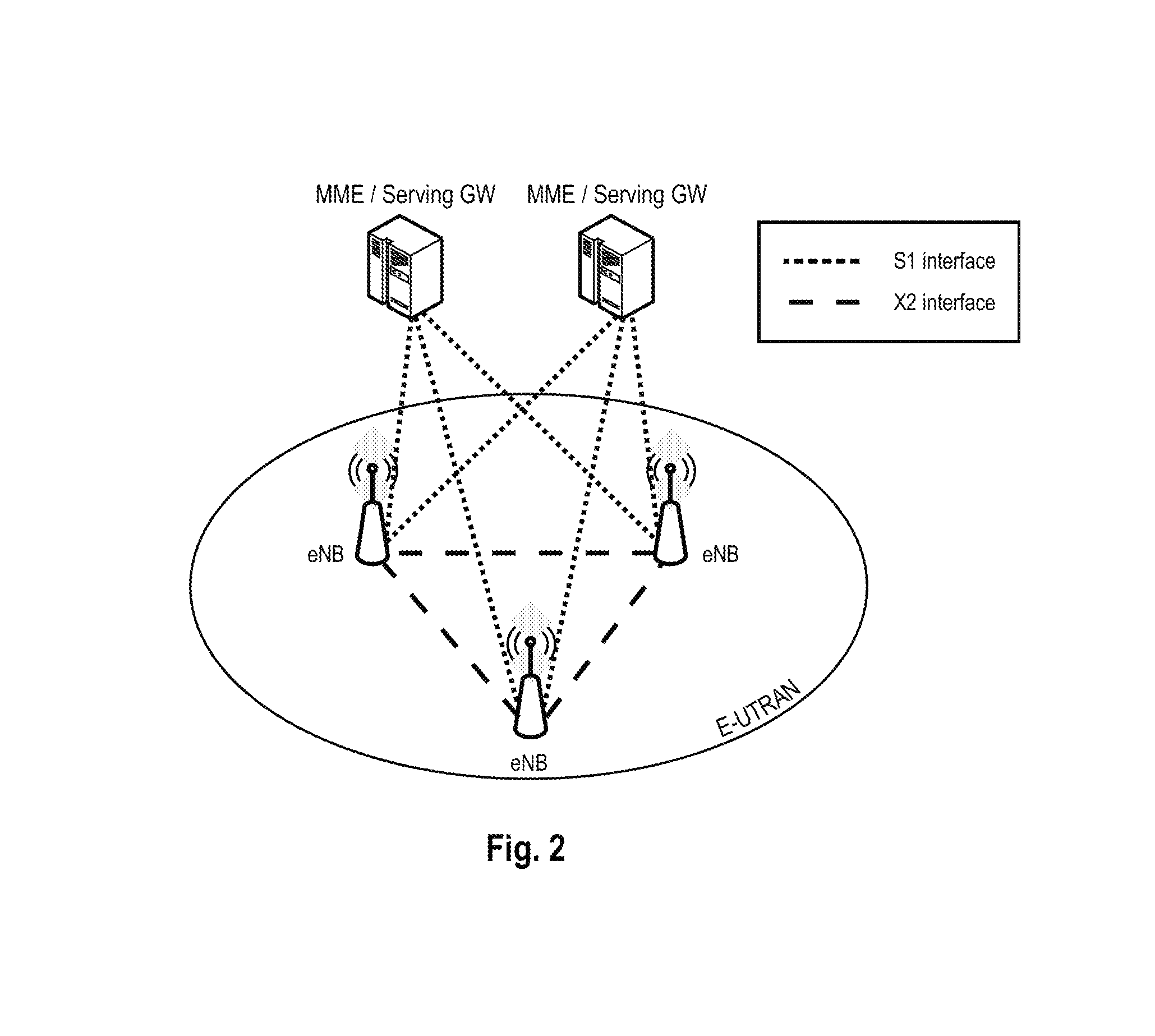
[0229]The following paragraphs will describe various embodiments of the invention. For exemplary purposes only, most of the embodiments are outlined in relation to the LTE-Advanced (LTE-A) mobile communication system discussed in the Technical Background section above. It should be noted that the invention may be advantageously used for example in connection with a mobile communication system such as the LTE-Advanced communication system previously described, but the invention is not limited to its use in this particular exemplary communication network.

[0230]The explanations given in the Technical Background section above are intended to better understand the mostly LTE-Advanced specific exemplary embodiments described herein and should not be understood as limiting the invention to the described specific implementations of processes and functions in the mobile communication network. Nevertheless, the improvements proposed herein may be readily applied in the architectures / systems d...


PUM


Abstract

The invention relates to a method for transmitting power headroom information from a user equipment to the base station. The transmission is made dependent on scheduling type of the uplink resource, for which the power headroom information is to be calculated and over which it is to be transmitted. If the uplink resource is dynamically scheduled, then the extended power headroom report according to Rel. 10 is transmitted; if it is scheduled persistently, e.g. as part of a semi-persistent scheduling configuration, then a basic power headroom report according to Rel. 8 / 9 is transmitted. The invention circumvents the problem of delaying data in persistently allocated uplink resources when transmitting an extended power headroom report.

Description

FIELD OF THE INVENTION[0001]The invention relates to a method for transmitting power headroom information from a user equipment to a base station, and to a user equipment for performing said method.TECHNICAL BACKGROUNDLong Term Evolution (LTE)[0002]Third-generation mobile systems (3G) based on WCDMA radio-access technology are being deployed on a broad scale all around the world. A first step in enhancing or evolving this technology entails introducing High-Speed Downlink Packet Access (HSDPA) and an enhanced uplink, also referred to as High Speed Uplink Packet Access (HSUPA), giving a radio-access technology that is highly competitive.[0003]In a longer time perspective it is however necessary to be prepared for further increasing user demands and be competitive against new radio access technologies. To meet this challenge, 3GPP has initiated the study item Evolved UTRA and UTRAN, aiming at studying means for achieve additional substantial leaps in terms of service provisioning and ...

Claims


Application Information

Patent Timeline
IPC IPC(8): H04W52/36
CPCH04W52/365H04W52/34H04W72/56H04W72/569H04W72/20
Inventor LOEHR, JOACHIMWENGERTER, CHRISTIANFEUERSAENGER, MARTINTAMURA, TAKASHI
Owner PANASONIC INTELLECTUAL PROPERTY CORP OF AMERICA
Learn More