Check patentability & draft patents in minutes with Patsnap Eureka AI!

Leaf spring system

a leaf spring and spring technology, applied in the field of leaf spring systems, can solve the problems of inability to meet the needs of day vehicles, the most susceptible component of vehicles to damage, and the inability to meet the needs of domestic applications, and achieve the effect of improving the spring characteristics of leaf springs

Active Publication Date: 2014-01-30
MOLNAR ELIZABETH ANNE
View PDF13 Cites 2 Cited by
  • Summary
  • Abstract
  • Description
  • Claims
  • Application Information

AI Technical Summary

Benefits of technology

The invention provides a leaf spring system that uses a reinforcing spring to improve the spring characteristics of the leaf spring. The reinforcing spring is attached to the leaf spring assembly and has at least one section that provides resilience to the leaf spring system. The at least one attachment mechanism connects the reinforcing spring to the leaf spring assembly and allows for sliding movement of the leaf springs during operation. This allows the leaf spring assembly to stretch and improves its spring characteristics.

Problems solved by technology

A vehicle's suspension is a component of the vehicle most susceptible to damage and it is often overlooked.
However, this often is not possible with present day vehicles on the market as they generally all follow the same industry standard and have not addressed the carrying problem.
The prior art has failed to provide a soft and comfortable ride as well as the correct carrying ability thereby creating maximum sag under full load.
There are serious issues for owners who are aware of the vehicle's carrying capacity but cannot achieve it because the springs are unable to constantly carry the load stipulated by the manufacturers.
Therefore spring damage can be caused by the owner believing the vehicle is capable of carrying the full pay load placed upon it.
It is the carrying ability and overall wear and tear that causes serious safety issues with the vehicle and the driver.
In particular, steering and braking is seriously compromised by a soft and sagging suspension.
During the carrying of such a load, the vehicle becomes unsafe and unroadworthy as spring sagging reduces the traction to front wheels and stability control of the vehicle and reduces braking performance.
When the vehicle is carrying a heavy load, the vehicle is so weighed down to possibly cause the load to rock and sway.
The wheels of the vehicle most likely will also often hard bounce off the road surface upon hitting bumps.
The prior art generally fails in providing a method of reducing or eliminating sagging and ensuring that the vehicle is safe to handle when carrying a heavy load by stabilizing body roll and improving braking performance.
In addition, the prior art fails in providing a method of reducing or eliminating rear spring sagging caused by the attachment of the vehicle to a trailer.
A common though low effectiveness technique provided by the prior art is to have the springs reset with an extra leaf.
This requires removing the spring leaf assembly from the vehicle and is an expensive, timely and labour intensive process.
In addition, the result of this technique causes an uncomfortable ride when no load is carried by the vehicle and inevitably, sagging will occur generally within 12 to 24 months if continuous maximum load is carried.
This is not commonly or generally known disclosure, however, such prior art documents have resulted in a number of significant disadvantages described herein.
The tensioning of u-bolts at the rear of the leaf spring system in this patent application are unable to sustain continuous weight and movement in the forward and backward motion as the major spring pack flexes and the length of the spring is increased and decreased.
Therefore the u-bolts are prone to snapping and breaking.
However, in the patent application, the inverted u-bolt further limits the distance between the load helper and the chassis rail and can therefore damage the chassis if the vehicle, for example, goes over a bump.
In addition, the u-bolt can be over tightened and cause spring breakage.
One of the major problems in the prior art is the spring slippage or dislodgement of the spring which occurs as the leaf spring assembly is trying to move with the u-bolt as it is not designed to move independently in the backwards and forwards direction.
Therefore, the prior art lacks the ability to provide a suspension system with leaf spring assemblies to improve ride quality, load carrying capacity, towing and handling improvements, all of which add up to safer, more comfortable and enjoyable driving experience and achieve minimum sag to the rear of the vehicle.

Method used


Image

  • Leaf spring system
  • Leaf spring system
  • Leaf spring system

Examples


first embodiment

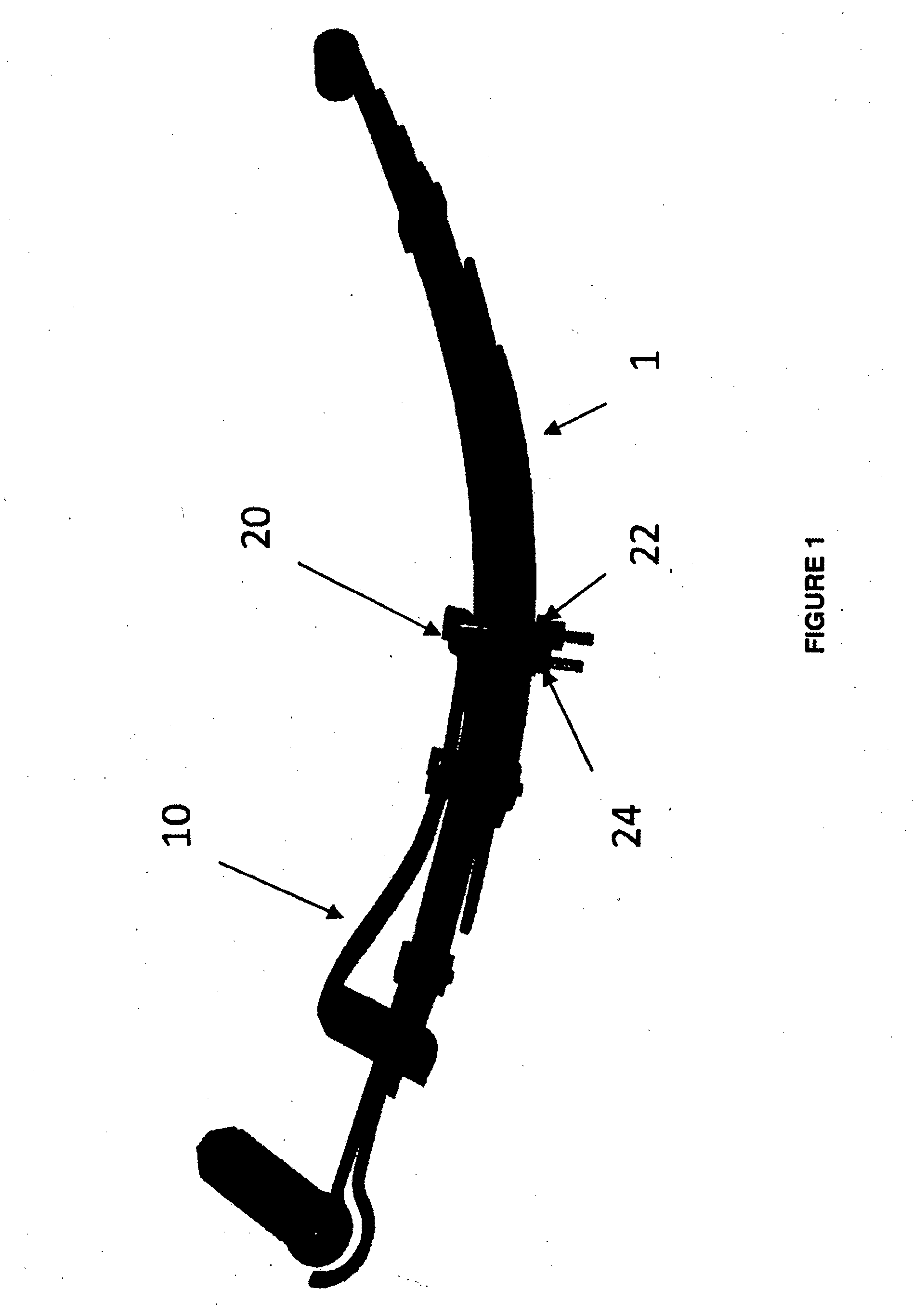
[0081]The reinforcing spring 10 is mounted to a back or shackle end of the leaf spring assembly 1. Thus, in the first embodiment the reinforcing spring 10 operates relative to a back half of the leaf spring assembly.

[0082]However, it is envisaged that the invention can be modified in order to allow the reinforcing spring 10 to attach to the leaf spring assembly 1.

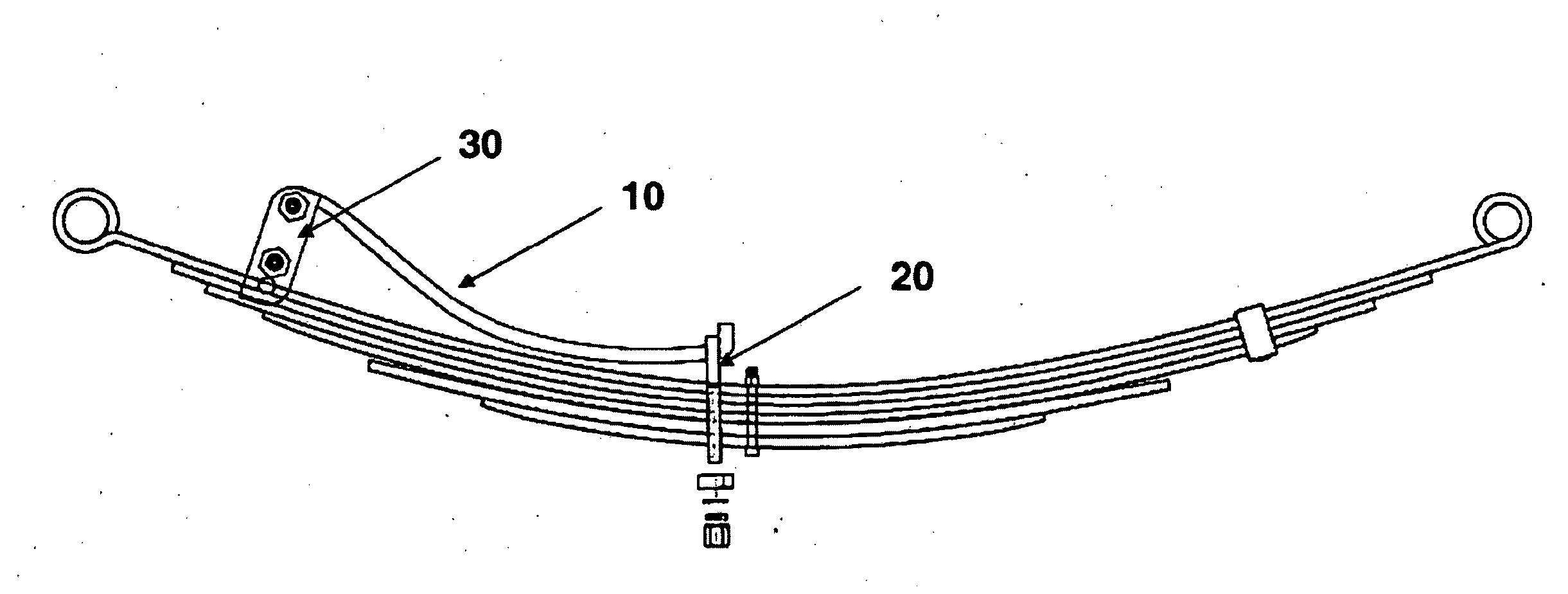
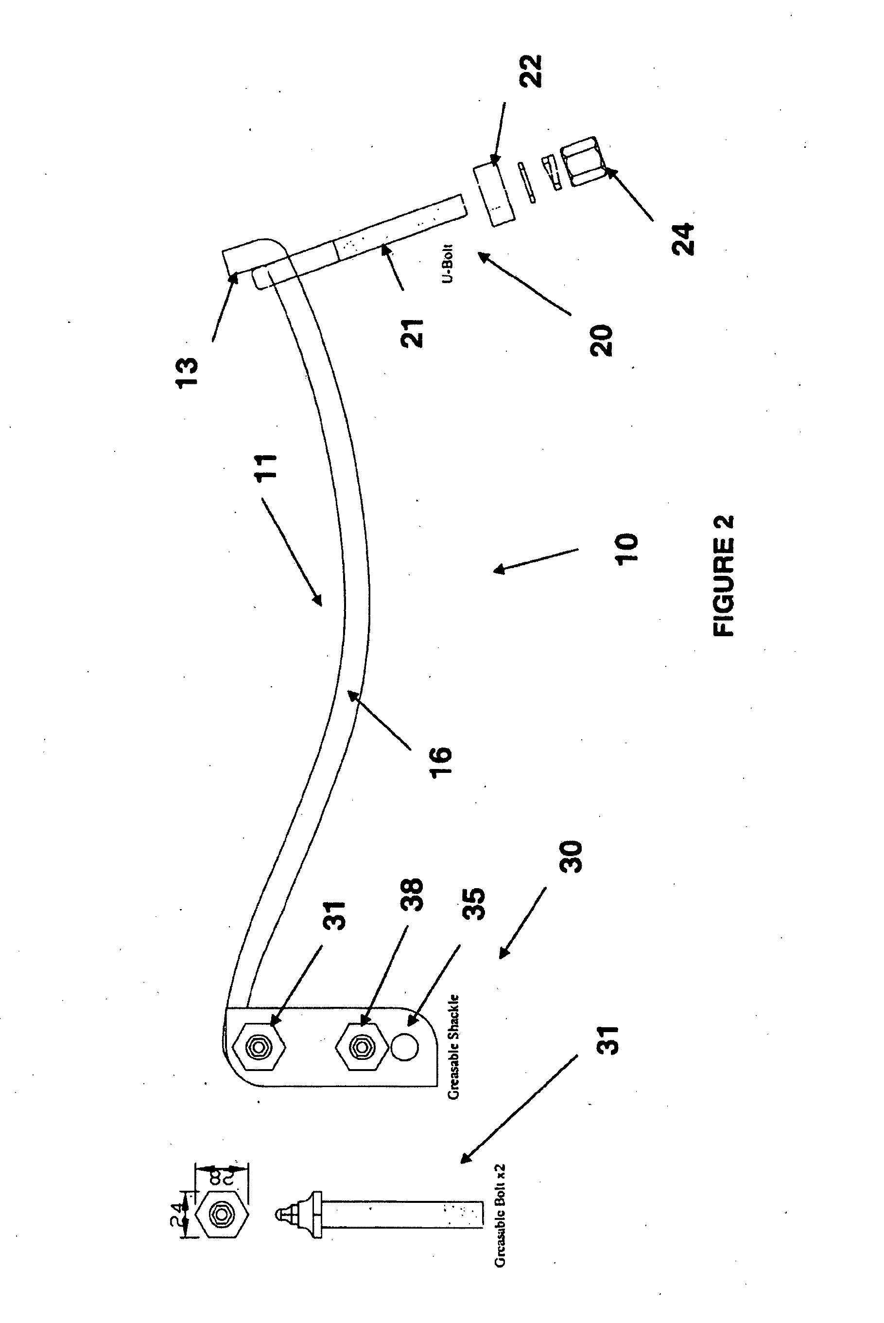
[0083]Referring to FIGS. 1 to 4C, it is shown that the reinforcing spring 10 comprises of a preformed curve shaped body portion 11 mounted to the leaf spring assembly 1 between a first attachment mechanism 30 and a second attachment mechanism 20.

[0084]The preformed curve shaped body portion 11 has a first end 14, a second end 13 and a connecting member 16. Thus, the first end 14 points towards the shackle end of the leaf spring assembly with the second end pointing towards a front or fixed pin end. The reinforcing spring 10 has a preformed prestressed body portion forming primarily the connecting member 16. The reinforcing ...

second embodiment

[0089]In a second embodiment, the first end 14 and / or second end 13 can be formed into a cupping feature. In such an embodiment, the cupping features provide a rotational motion around the attachment mechanism 30.

[0090]The second end 13 assists in connecting, locking or securing into position the second attachment mechanism 20 to connect the reinforcing spring 10 to the leaf pack assembly 1. In the embodiment presented in FIG. 2, the second end 13 is in the form of an outwardly protruding member that is adjacent in a right angle to the connecting member 16. In alternative embodiment, the second end can be provided with apertures in which to house the second attachment mechanism.

[0091]The first attachment mechanism 30 can, in one form, be a shackle. In this form, the first attachment mechanism 30 comprises of a plurality of plates 32 and the first connector 31 in the form of male and female components for fitment to a brass bush. The brass bush provides an interference fit. In doing ...


PUM

PropertyMeasurementUnit
lengthaaaaaaaaaa
heightaaaaaaaaaa
lengthaaaaaaaaaa

Abstract

The invention provides a leaf spring system which supports a leaf spring assembly using attachment mechanisms which allows normal operation of the leaf spring assembly while providing support through a resilient deformable reinforcing spring.

Description

FIELD OF THE INVENTION[0001]The present invention generally relates to a leaf spring system and in particular to improving spring characteristics of such a leaf spring assembly using the leaf spring system.[0002]Whilst the invention may be applied to any type of vehicle having a suspension system, for convenience sake it shall be described herein used by a motor vehicle.BACKGROUND TO THE INVENTION[0003]A vehicle's suspension is a component of the vehicle most susceptible to damage and it is often overlooked. The issue of spring sag in motor vehicles is a common aspect, often arising as manufacturers opt to go for comfort rather attain carrying ability. The consumer being unaware, expects the vehicle to carry full payload upon demand. However, this often is not possible with present day vehicles on the market as they generally all follow the same industry standard and have not addressed the carrying problem. The prior art has failed to provide a soft and comfortable ride as well as t...

Claims


Application Information

Patent Timeline
Patent Type & Authority Applications(United States)
IPC IPC(8): B60G11/02B21D53/88F16F1/18
CPCB60G11/02B21D53/886F16F1/18B60G2204/121F16F1/22F16F1/26Y10T29/49609
Inventor MOLNAR, JOHN
Owner MOLNAR ELIZABETH ANNE
Features
  • R&D
  • Intellectual Property
  • Life Sciences
  • Materials
  • Tech Scout
  • Unparalleled Data Quality
  • Higher Quality Content
  • 60% Fewer Hallucinations
Learn More