Supercharge Your Innovation With Domain-Expert AI Agents!

Unit comprising an electric power source including at least two elements of different technologies and an inverter for controlling an alternating-current electric motor

a technology of electric motor and inverter, which is applied in the direction of motor/generator/converter stopper, dynamo-electric converter control, propulsion by batteries/cells, etc., can solve the problems of not allowing very dynamic regulation, not allowing good current control, and affecting the correct regulation of discharge current in this manner

Inactive Publication Date: 2014-04-24
MICHELIN & CO CIE GEN DES ESTAB MICHELIN +1
View PDF7 Cites 2 Cited by
  • Summary
  • Abstract
  • Description
  • Claims
  • Application Information

AI Technical Summary

Benefits of technology

The invention proposes an installation for controlling an electric motor using an electrical energy source comprising at least two elements of different technologies. The installation includes an inverter for controlling the electric motor, a supply line for delivering current to the motor, a current measurement line for measuring the current on the supply line, and a controller for controlling the motor's phase currents while keeping the current passing through the supply line at a desired level. The invention can be applied to vehicles and can manage the flow of energy from various sources such as batteries, super-capacitors, or fuel cells. The technical effect of the invention is to provide an efficient and flexible way to control the electric motor while optimizing the use of different technologies for energy storage and management.

Problems solved by technology

This arrangement does not allow very dynamic regulation.
But this principle does not allow good command of the current in the case of certain types of battery, such as Li-Ion batteries, for example, whose use is tending to spread.
The voltage of Li-ion batteries indeed depends on numerous factors (temperature, state of charge, aging) and it is very problematic to correctly regulate a discharge current in this manner.
In particular, it describes a limitation of the consumption of the current of the source by way of motor control, the said limitation being based on a modelling of the motor, that is to say the establishment of a mapping of the motor as a function of various parameters.
This approach is not optimal because it is difficult to perform a modelling that is sufficiently representative of all elements in all cases of use.
This approach (modelling) therefore leads to the full power of the source not being used in cases where the real losses are lower than those estimated (low temperature for example) and it does not take account of the aging and therefore of the loss of efficiency of the inverter or of the motor.
Thus, maximum performance is not guaranteed under all conditions.

Method used


Image

  • Unit comprising an electric power source including at least two elements of different technologies and an inverter for controlling an alternating-current electric motor
  • Unit comprising an electric power source including at least two elements of different technologies and an inverter for controlling an alternating-current electric motor
  • Unit comprising an electric power source including at least two elements of different technologies and an inverter for controlling an alternating-current electric motor

Examples


Embodiment Construction

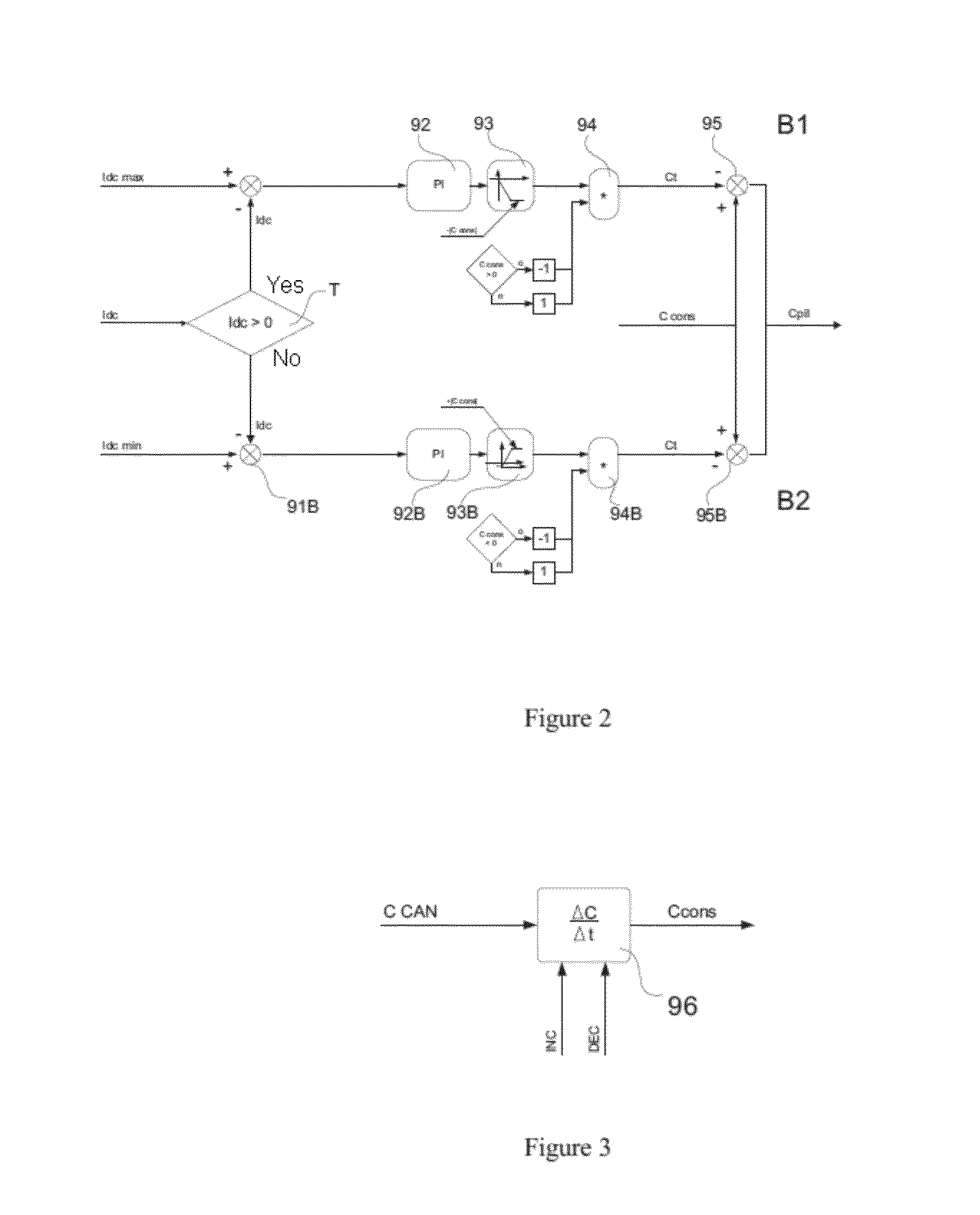
[0036]In FIG. 1 may be seen an inverter 1, a three-phase electric motor 6, a battery 8 constituting the DC electrical energy source and a CAN ® bus 7 on which there flows information used by the inverter 1. The three-phase electric motor comprises a stator having at least three phases U, V, W and a rotor.

[0037]The inverter 1 comprises two terminals 2 and 10 for attachment to a DC bus (direct current bus) associated with a DC electric voltage and DC electrical energy source. It comprises an AC current generator 3 delivering a current to a terminal strip 4 intended to be connected to the phases U, V and W of the said electric motor 6. The inverter 1 comprises a supply line 20 between the terminal 2 and the current generator 3. The inverter 1 comprises a controller 5 and a control stage 9 receiving control orders from the controller 5 and ensuring the control of the power transistors of the current generator 3.

[0038]In a preferred implementation of the invention, so as to allow control...


PUM


Abstract

An installation for an electric motor includes an electrical energy source with elements of different technologies and an inverter for controlling an AC electric motor. The inverter includes an AC current generator for delivering current to a terminal strip to be connected to phases of the electric motor, a supply line, current sensors on certain phases supplying the electric motor, a current sensor on the supply line, an input for receiving information that includes a limit current of the source and a requested-torque setpoint, and a controller for controlling phase currents of the electric motor as a function of the setpoint while maintaining a current of the supply line at an acceptable value as a function of the limit current of the source. The installation makes it possible to impose a maximum current on the current generator without risk of impairing the current generator.

Description

FIELD OF THE INVENTION[0001]The present invention pertains to the control of electric motors. More particularly, it pertains to the control of the electric motors used especially for vehicle traction.PRIOR ART[0002]It is known that such a motor comprises, at the stator, a magnetic circuit and electrically conducting wire coils capable of producing a stator magnetic flux. In the case of a synchronous motor, at the rotor, the motor comprises permanent magnets and a magnetic circuit producing a rotor magnetic flux. In the case of an asynchronous motor, the motor comprises a squirrel cage rotor. In the case of a reluctant motor, the motor comprises a reluctant rotor. In many applications for electric vehicles, synchronous motors are used. Such a motor is equipped with a “resolver” giving the position of the rotor with respect to the stator. Such a motor is always associated with an inverter to ensure the control thereof[0003]The person skilled in the art knows that, in practice, electri...

Claims


Application Information

Patent Timeline
Patent Type & Authority Applications(United States)
IPC IPC(8): H02P6/00
CPCH02P6/002H02P6/28B60L50/51Y02T10/72Y02T10/70Y10S388/9072
Inventor MODOLO, IVAN
Owner MICHELIN & CO CIE GEN DES ESTAB MICHELIN
Features
  • R&D
  • Intellectual Property
  • Life Sciences
  • Materials
  • Tech Scout
  • Unparalleled Data Quality
  • Higher Quality Content
  • 60% Fewer Hallucinations
Learn More