Unlock instant, AI-driven research and patent intelligence for your innovation.

Cell connection control device

a control device and cell technology, applied in the direction of secondary cell servicing/maintenance, cell components, safety/protection circuits, etc., can solve the problem of taking the time required to complete the parallel-connection of the cells, and achieve the effect of parallel-connecting the cells in a short time and suppressing excessive inrush curren

Active Publication Date: 2014-11-27
NISSAN MOTOR CO LTD
View PDF0 Cites 3 Cited by
  • Summary
  • Abstract
  • Description
  • Claims
  • Application Information

AI Technical Summary

Benefits of technology

The present invention provides a device for controlling the connection between cells in a battery. The device can quickly connect multiple cells in parallel while minimizing the high current that occurs when multiple cells are connected at the same time. The device calculates the current for each combination of cells and selects the combination with the highest current as the best option for connection. This allows for quick and efficient parallelization of cells without causing unnecessary damage.

Problems solved by technology

However, in the case of a method disclosed in the Patent Document 1, since the lower voltage cell is charged and its voltage is made equal to voltage of the higher voltage cell, a process (an operation) to connect the cell to a charger and also a process (an operation) to charge the cell are needed, then there arises a problem of taking time required to complete the parallel-connection of the cells.

Method used


Image

  • Cell connection control device
  • Cell connection control device
  • Cell connection control device

Examples


first embodiment

[0015]FIG. 1 is a block diagram showing a cell connection system according to the present embodiment. As shown in FIG. 1, a cell connection system 100 of the present embodiment is a system that connects n cells in parallel from m cells previously prepared (where, n≦m). The cell connection system 100 has a cell connection control device 10, a cell connection device (or a cell connection unit) 20, a voltage sensor 50 and a current sensor 60 which detect voltage and current of each cell. Parallel-connected cells work as a battery module that supplies power to an electrical load 30.

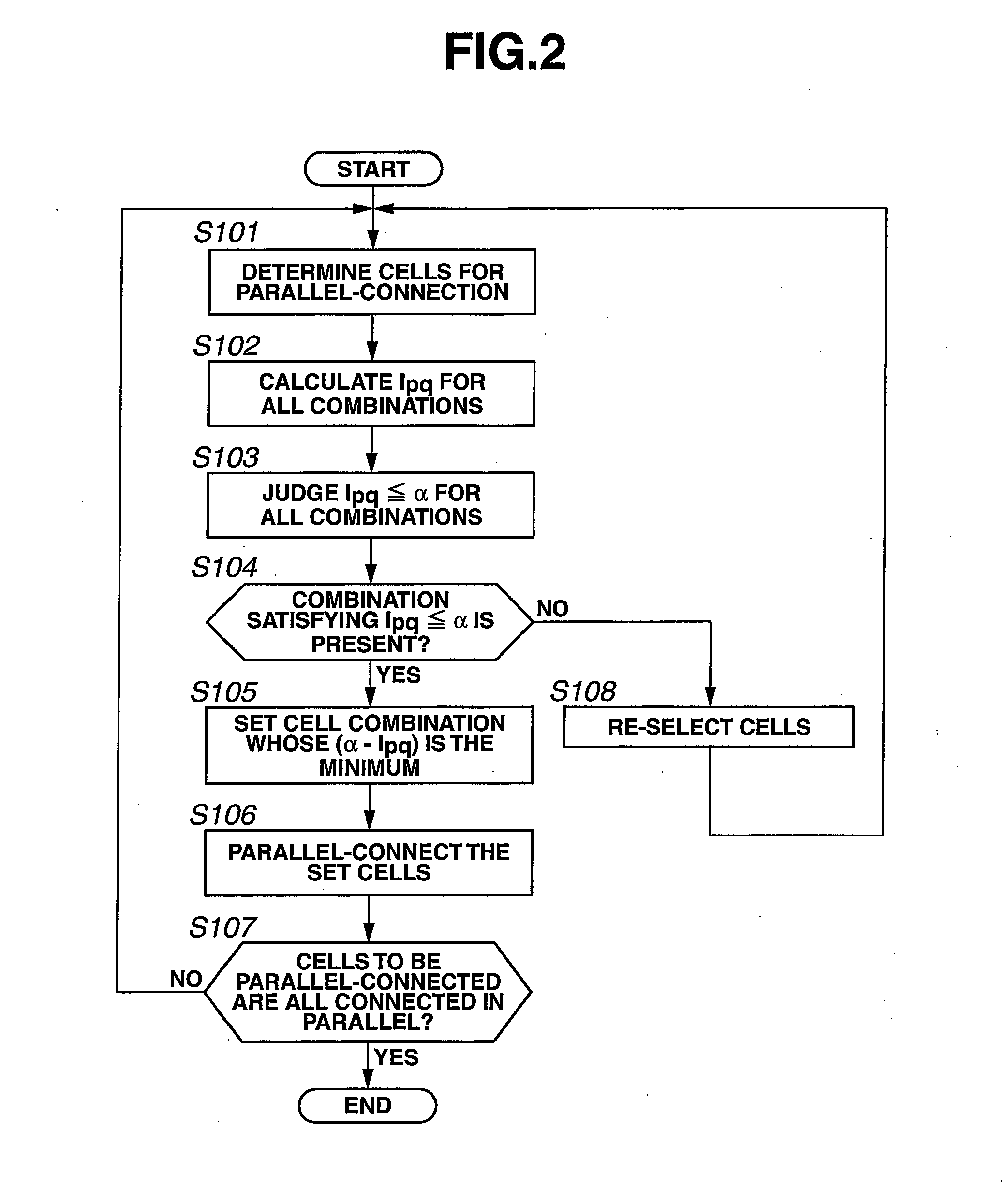
[0016]The cell connection control device 10 is a device that sets a cell combination to parallel-connect the cells from the plurality of cells. More specifically, the cell connection control device 10 performs an operation to select a pair of cells from the cells for the parallel-connection of the cells and to calculate an inrush current that is current flowing between the selected pair of cells when parallel...

second embodiment

[0035]Next, a second embodiment of the present invention will be explained. FIG. 3 is a flow chart showing the other example of the operation in which the cell combination to parallel-connect the cells is set from the plurality of cells and the set cells are parallel-connected. Regarding operation steps of the present embodiment, steps S101˜S108 are the same as those of the first embodiment shown in FIG. 2. Thus, these steps in FIG. 3 are indicated by the same step numbers as those in FIG. 2, and description of their explanation mentioned above is used also in the present embodiment. Further, a configuration of the cell connection system of the present embodiment is the same as that shown in FIG. 1.

[0036]With regard to a specific method of the second embodiment which sets the cell combination to parallel-connect the cells from the plurality of cells, as same as the first embodiment, the case where the previously sampled or selected n cells (n is an arbitrary number of cells with m b...

third embodiment

[0057]Next, a third embodiment of the present invention will be explained. The third embodiment is an embodiment obtained by modifying the second embodiment. FIG. 4 is a flow chart of the third embodiment, showing an operation in which the cell combination to parallel-connect the cells is set from the plurality of cells and the set cells are parallel-connected. In the present embodiment, the cell combination to parallel-connect the cells is set, and after parallel-connecting the pair of cells forming the set cell combination, the routine returns to step S201, then the magnitude of the variation of the internal resistance of the cell is judged again. This point is different as compared with the second embodiment.

[0058]By this operation, in the present embodiment, the cell combination to parallel-connect the cells is set, and after parallel-connecting the pair of cells forming the set cell combination, a judgment is made again as to whether or not the variation of the internal resista...


PUM


Abstract

When connecting a plurality of cells in parallel, an operation to calculate an inrush current flowing when a pair of cells are selected from the cells for the parallel-connection and parallel-connected for all cell combinations. A cell combination, whose inrush current is the largest in the cell combinations which are judged that the calculated inrush current is less than or equal to a predetermined upper limit current value, is set as a cell combination to parallel-connect the cells.

Description

TECHNICAL FIELD[0001]The present invention relates to a cell connection control device.BACKGROUND ART[0002]There has been known a technique in which when connecting a plurality of battery packs in parallel, in a case where there is a voltage difference between each of cells, in order to prevent an excessive inrush current from flowing from a higher voltage cell to a lower voltage cell, the cells are connected in parallel after the lower voltage cell is charged so that potential difference becomes a predetermined level or less (see e.g. Patent Document 1).[0003]Here, when the excessive inrush current flows in the cell upon parallel-connecting the plurality of cells, there is a possibility that life of the battery (the cell) will be shortened and / or heat generation of the battery (the cell) will occur. Thus, while it is required that the excessive inrush current be surely prevented from flowing in the cell, a method of parallel-connecting the plurality of cells in a short time is desi...

Claims


Application Information

Patent Timeline
IPC IPC(8): H01M10/42H01M10/48H02J1/10H02J7/02
CPCH01M10/4257H02J1/10H01M2010/4271H02J2001/008H01M10/482H02J7/00304Y02E60/10H02J1/082
Inventor MATSUYAMA, CHIDURUTSUKAMOTO, YUKARIFUJITA, TAKESHI
Owner NISSAN MOTOR CO LTD