Check patentability & draft patents in minutes with Patsnap Eureka AI!

Optical system for posture detection comprising a scanning light source and a cube corner

a scanning light source and optical system technology, applied in the direction of instruments, measurement devices, apparel, etc., can solve the problems of affecting the stealth of the aircraft, large part of the light intensity is lost, and the retro-reflector system is relatively insensitive to sunlight, so as to avoid the loss of measurement time and energy loss

Active Publication Date: 2015-04-16
THALES SA
View PDF1 Cites 0 Cited by
  • Summary
  • Abstract
  • Description
  • Claims
  • Application Information

AI Technical Summary

Benefits of technology

The invention is a system that can detect the posture of a moving object using a scanning light source. This system avoids energy loss and measurement time by centering the scanning over the useful region of the retro-reflector. The technical effect of the invention is the accurate and efficient detection of the posture of a mobile object in space.

Problems solved by technology

These retro-reflector systems are relatively insensitive to sunlight.
However this technical solution has certain drawbacks.
A very large part of the light intensity is therefore always lost, since it does not reach the reflector.
This part of the light is, moreover, radiated into the surrounding space, inside and outside of the cabin, thus being detrimental to the stealth of the aircraft.
The overall uncertainty in the orientation measurement cumulates the error of each of these two measurements.
The duration of the measurement cycle is limited by the time for addressing an image sensor array, i.e. around 16 ms, which can lead to a measurement error in the case of a high-speed rotation of the mobile object.

Method used


Image

  • Optical system for posture detection comprising a scanning light source and a cube corner
  • Optical system for posture detection comprising a scanning light source and a cube corner
  • Optical system for posture detection comprising a scanning light source and a cube corner

Examples


Embodiment Construction

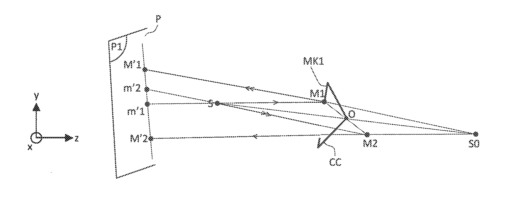
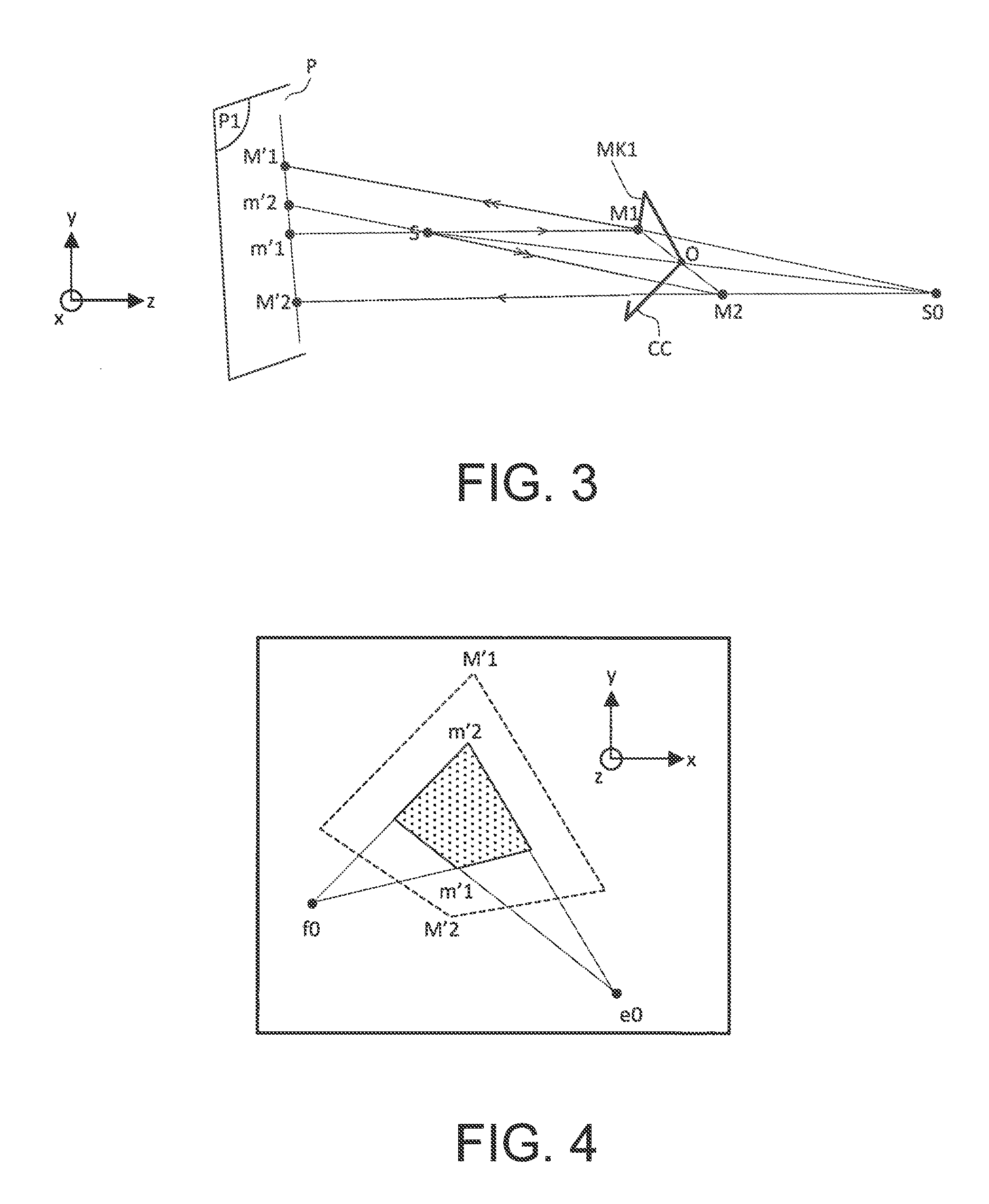
[0045]FIG. 3 shows the principle of operation of a posture detection system according to the invention. The detection system essentially comprises a fixed assembly of known position and a mobile assembly. The fixed assembly comprises an electro-optical device of known orientation comprising a light source S, a single photoreceptor P disposed in a plane P1 and a means for analyzing signals coming from the said photoreceptor which is not shown in FIG. 3. P1 is parallel to a plane (x, y). The mobile assembly comprises a cube corner CC disposed on a mobile object whose posture it is sought to determine, the said cube corner comprising a mask of known geometrical shape disposed on its entry face. The mobile object is not shown in the various figures. In the case of aeronautical applications, this will be the helmet of the pilot.

[0046]The light source S is a point-like source. It emits a thin pencil beam of light. Scanning means provide the angular displacement of this pencil beam about S...


PUM


Abstract

The general field of the invention is that of systems for detecting the posture of a mobile object in space. The system according to the invention comprises an electro-optical device comprising a light source, a photoreceptor and means of analysis, and a retro-reflecting cube corner disposed on the mobile object. The cube corner comprises a mask disposed on its entry face. The source emits a parallel or almost-parallel pencil beam. The electro-optical device comprises means for deviating, about a fixed point, the said pencil beam of light by an angle varying as a function of time. The photoreceptor is configured for receiving the pencil beam of light retro-reflected by the cube corner. The means of analysis are configured in such a manner as to determine, based on the signal coming from the photoreceptor, the position of a number of points representative of the borders of the mask and, using this positional information, the posture of the cube corner in space.

Description

CONTEXT OF THE INVENTION[0001]1. Technical Field of the Invention[0002]The field of the invention is that of optical devices allowing the orientation of an object in space to be measured without contact. There exist various possible fields of applications, but the main application is posture detection for a helmet of an aircraft pilot, thus allowing an image to be projected into his / her visor in exact superposition over the external scene or various systems of the aircraft to be closed-loop controlled onto his / her gaze. The precision sought in such systems is of the order of a milliradian. In the description that follows, the posture of an object is understood to mean its position and its orientation in space.[0003]2. Description of the Prior Art[0004]Various optical techniques exist that allow measurements of orientation to be made on a helmet. Generally speaking, easily-identifiable elements are installed on the helmet which are picked out by a system of cameras. The position of t...

Claims


Application Information

Patent Timeline
IPC IPC(8): G01B11/14A42B3/00
CPCG01B11/14A42B3/00G01S17/46G01S17/74
Inventor BARBIER, BRUNOPOTIN, LAURENTROUZES, SIEGFRIED
Owner THALES SA
Features
  • R&D
  • Intellectual Property
  • Life Sciences
  • Materials
  • Tech Scout
  • Unparalleled Data Quality
  • Higher Quality Content
  • 60% Fewer Hallucinations
Learn More