Magnetic head for perpendicular magnetic recording including a heater
a perpendicular magnetic and recording head technology, applied in the direction of maintaining the head carrier alignment, recording information storage, instruments, etc., can solve the problems of insufficient reduction of the distance between the end face of the main pole and the surface of the recording medium, and inability to achieve sufficient recording density, etc., to achieve the effect of suppressing the protruding portion and increasing the amount of the end fa
- Summary
- Abstract
- Description
- Claims
- Application Information
AI Technical Summary
Benefits of technology
Problems solved by technology
Method used
Image


Examples
first embodiment
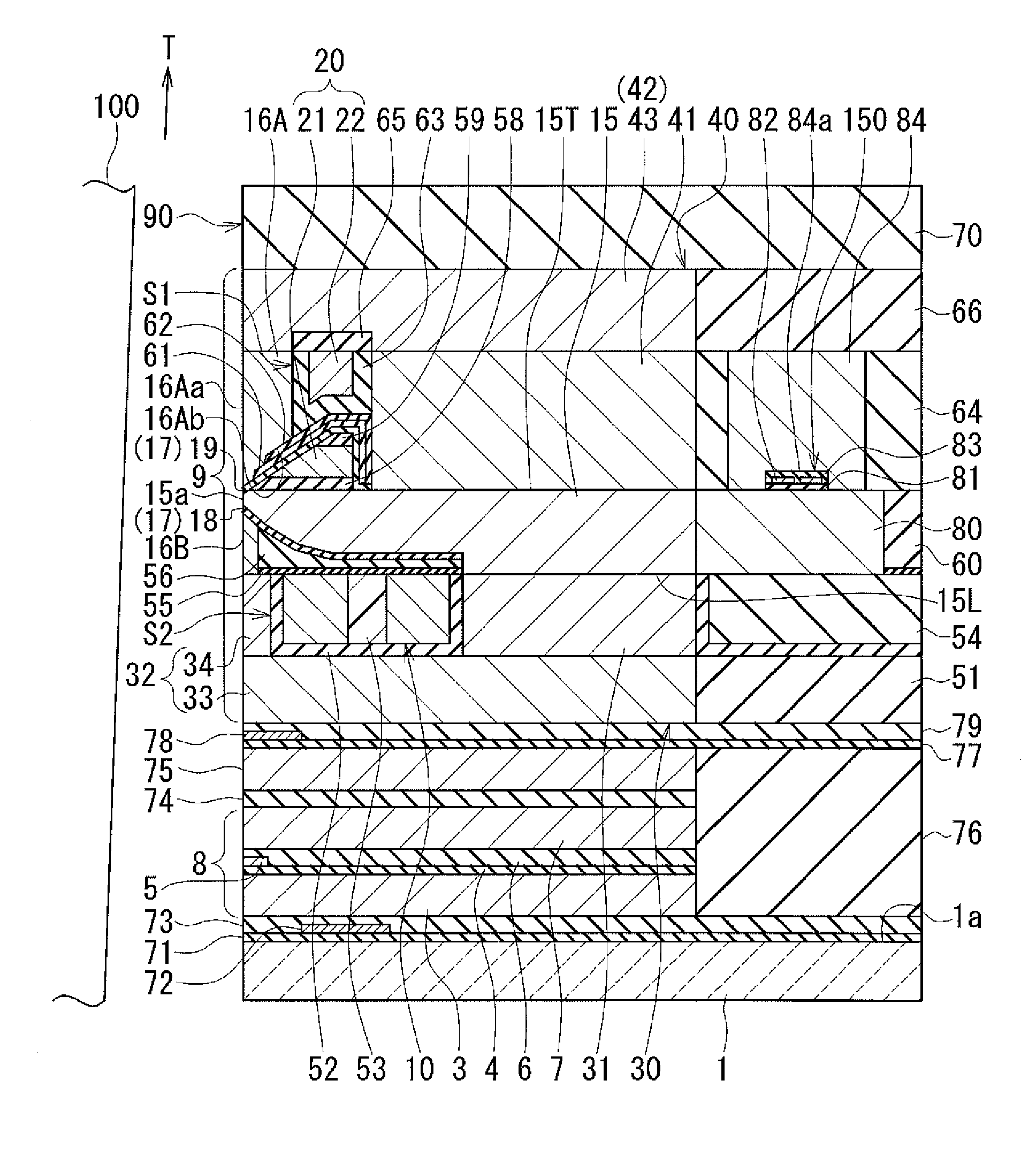
[0041]Preferred embodiments of the present invention will now be described in detail with reference to the drawings. First, reference is made to FIG. 1 to FIG. 6 to describe the configuration of a magnetic head according to a first embodiment of the invention. FIG. 1 is a cross-sectional view showing the magnetic head according to the present embodiment. The arrow with the symbol T in FIG. 1 indicates the direction of travel of a recording medium. FIG. 2 is a front view showing the medium facing surface of the magnetic head according to the present embodiment. FIG. 3 is a plan view showing a second portion of a coil of the magnetic head according to the present embodiment. FIG. 4 is a plan view showing a main pole, an expansion member and a heater of the magnetic head according to the present embodiment. FIG. 5 is a plan view showing a first layer of a first portion of the coil of the magnetic head according to the present embodiment. FIG. 6 is a plan view showing a second layer of ...
second embodiment
[0137]A magnetic head according to a second embodiment of the invention will now be described with reference to FIG. 9 to FIG. 11. FIG. 9 is a cross-sectional view of the magnetic head according to the present embodiment. Note that FIG. 9 shows the main cross section. FIG. 10 is a plan view showing a first layer of a second portion of the coil of the present embodiment. FIG. 11 is a plan view showing a first layer of the second portion of the coil of the present embodiment.
[0138]The configuration of the magnetic head according to the present embodiment differs from that of the magnetic head according to the first embodiment in the following ways. The second connecting portion 32 of the second return path section 30 of the present embodiment includes a magnetic layer 35 in addition to the magnetic layers 33 and 34. The magnetic layer 35 is located farther from the medium facing surface 90 than is the magnetic layer 34 and lies on the magnetic layer 33. In the present embodiment, the ...
third embodiment
[0145]A magnetic head according to a third embodiment of the invention will now be described with reference to FIG. 12 and FIG. 13. FIG. 12 is a plan view showing a second portion of the coil of the magnetic head according to the present embodiment. FIG. 13 is a plan view showing a first portion of the coil of the magnetic head according to the present embodiment.
[0146]The magnetic head according to the present embodiment differs from the magnetic head according to the first embodiment in the following ways. In the magnetic head according to the present embodiment, the coil is wound approximately two turns around the main pole 15. The coil of the present embodiment includes a second portion including two line-shaped portions 11 and 12 shown in FIG. 12, in place of the second portion 10 of the first embodiment shown in FIG. 3. The coil of the present embodiment further includes a first portion including a first layer 21 and a second layer 22 shaped as shown in FIG. 13, in place of th...
PUM
| Property | Measurement | Unit |
|---|---|---|
| thickness | aaaaa | aaaaa |
| thickness | aaaaa | aaaaa |
| height | aaaaa | aaaaa |
Abstract
Description
Claims
Application Information
 - R&D
- Intellectual Property
- Life Sciences
- Materials
- Tech Scout
- Unparalleled Data Quality
- Higher Quality Content
- 60% Fewer Hallucinations
Browse by: Latest US Patents, China's latest patents, Technical Efficacy Thesaurus, Application Domain, Technology Topic, Popular Technical Reports.
© 2025 PatSnap. All rights reserved.Legal|Privacy policy|Modern Slavery Act Transparency Statement|Sitemap|About US| Contact US: help@patsnap.com