Anisotropic Bonded Magnets

Inactive Publication Date: 2015-07-23
BOARD OF REGENTS
View PDF3 Cites 0 Cited by
  • Summary
  • Abstract
  • Description
  • Claims
  • Application Information

AI Technical Summary

Benefits of technology

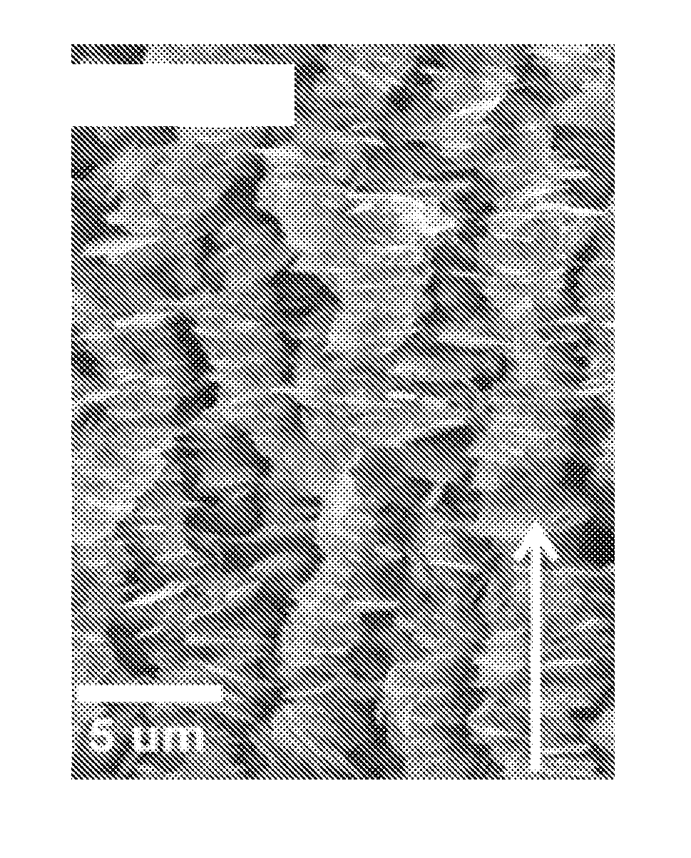
[0005]The present invention provides a product and process from fabricating anisotropic bonded magnets by surfactant-assisted ball milling in a magnetic field and magnetic field alignment of the milled chip-like nanoparticles of the Sm—Co and Nd—Fe—B materi

Problems solved by technology

However, there is a major disadvantage of bonded magnets: their energy density is substantially lower than sintered magnets, due to diluted magnetic components and the isotropic nature.
Though attempts have been made t

Method used


Image

  • Anisotropic Bonded Magnets
  • Anisotropic Bonded Magnets
  • Anisotropic Bonded Magnets

Examples


Embodiment Construction

[0020]While the making and using of various embodiments of the present invention are discussed in detail below, it should be appreciated that the present invention provides many applicable inventive concepts that can be embodied in a wide variety of specific contexts. The specific embodiments discussed herein are merely illustrative of specific ways to make and use the invention and do not delimit the scope of the invention.

[0021]To facilitate the understanding of this invention, a number of terms are defined below. Terms defined herein have meanings as commonly understood by a person of ordinary skill in the areas relevant to the present invention. Terms such as “a”, “an” and “the” are not intended to refer to only a singular entity, but include the general class of which a specific example may be used for illustration. The terminology herein is used to describe specific embodiments of the invention, but their usage does not delimit the invention, except as outlined in the claims.

[...


PUM

PropertyMeasurementUnit
Fractionaaaaaaaaaa
Fractionaaaaaaaaaa
Timeaaaaaaaaaa

Abstract

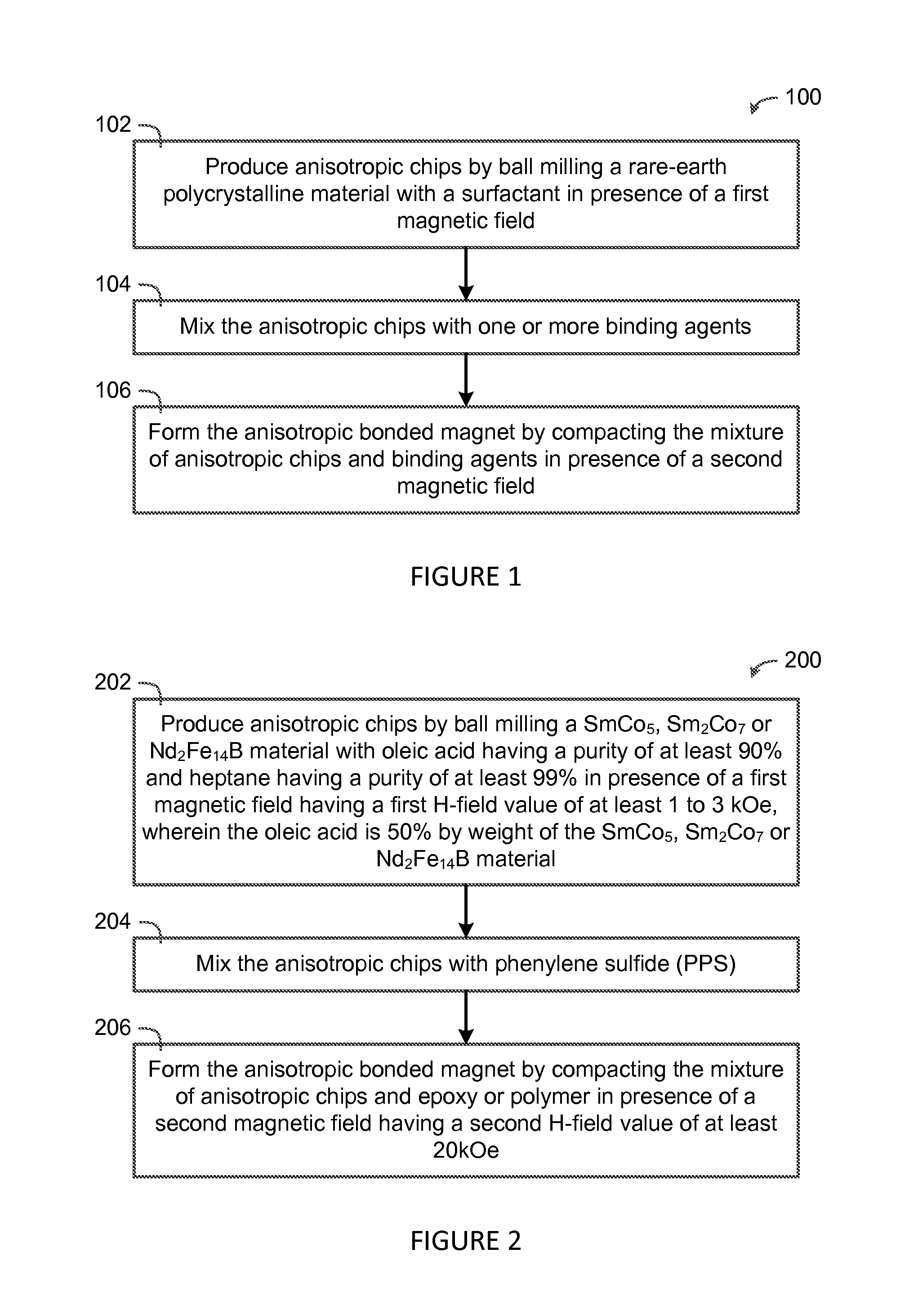
The present invention provides an anisotropic bonded magnet and a method for fabricating the anisotropic bonded magnet by producing anisotropic chips by ball milling a rare-earth polycrystalline material with a surfactant in presence of a first magnetic field, mixing the anisotropic chips with one or more binding agents, and forming the anisotropic bonded magnet by compacting the mixture of anisotropic chips and binding agents in presence of a second magnetic field.

Description

STATEMENT OF FEDERALLY SPONSORED RESEARCH OR DEVELOPMENT[0001]This invention was made with government support under Grant No. W911NF-08-1-0249 awarded by the U.S. Department of Defense / Defense Advanced Research Projects Agency / Army Research Office. The U.S. government has certain rights in the invention.FIELD OF INVENTION[0002]The present invention relates generally to the field of magnets and, more particularly, to anisotropic bonded magnets fabricated by surfactant-assisted ball milling and magnetic-field processing.BACKGROUND ART[0003]Improved permanent magnets are essential for emergent applications in electronic and electric devices [1-3]. While sintered permanent magnets are still the major type magnets for most applications, demand for bonded magnets is rapidly growing for the advantages of bonded magnets in part size and shape control which is particularly important for miniaturization of electronic devices [4]. However, there is a major disadvantage of bonded magnets: their...

Claims


Application Information

Patent Timeline
IPC IPC(8): H01F1/057H01F41/02B22F3/02H01F1/055
CPCH01F1/0578B22F3/02H01F41/0266H01F1/0558B22F2998/10B22F2999/00C22C2202/02B22F2202/05
Inventor LIU, J. PING
Owner BOARD OF REGENTS
Why Eureka
Try Eureka