

Control system for nitrogen and phosphorus removal
a control system and nitrogen and phosphorus technology, applied in sustainable biological treatment, biological water/sewage treatment, waste based fuel, etc., can solve the problems of deficient independent process control strategies, and achieve the effect of enhancing biological phosphorus removal
- Summary
- Abstract
- Description
- Claims
- Application Information
AI Technical Summary
Benefits of technology
Problems solved by technology
Method used
Image

Examples
example 1
Interrelatedness of Denitrification, EBPR and Chemical Phosphorus Removal
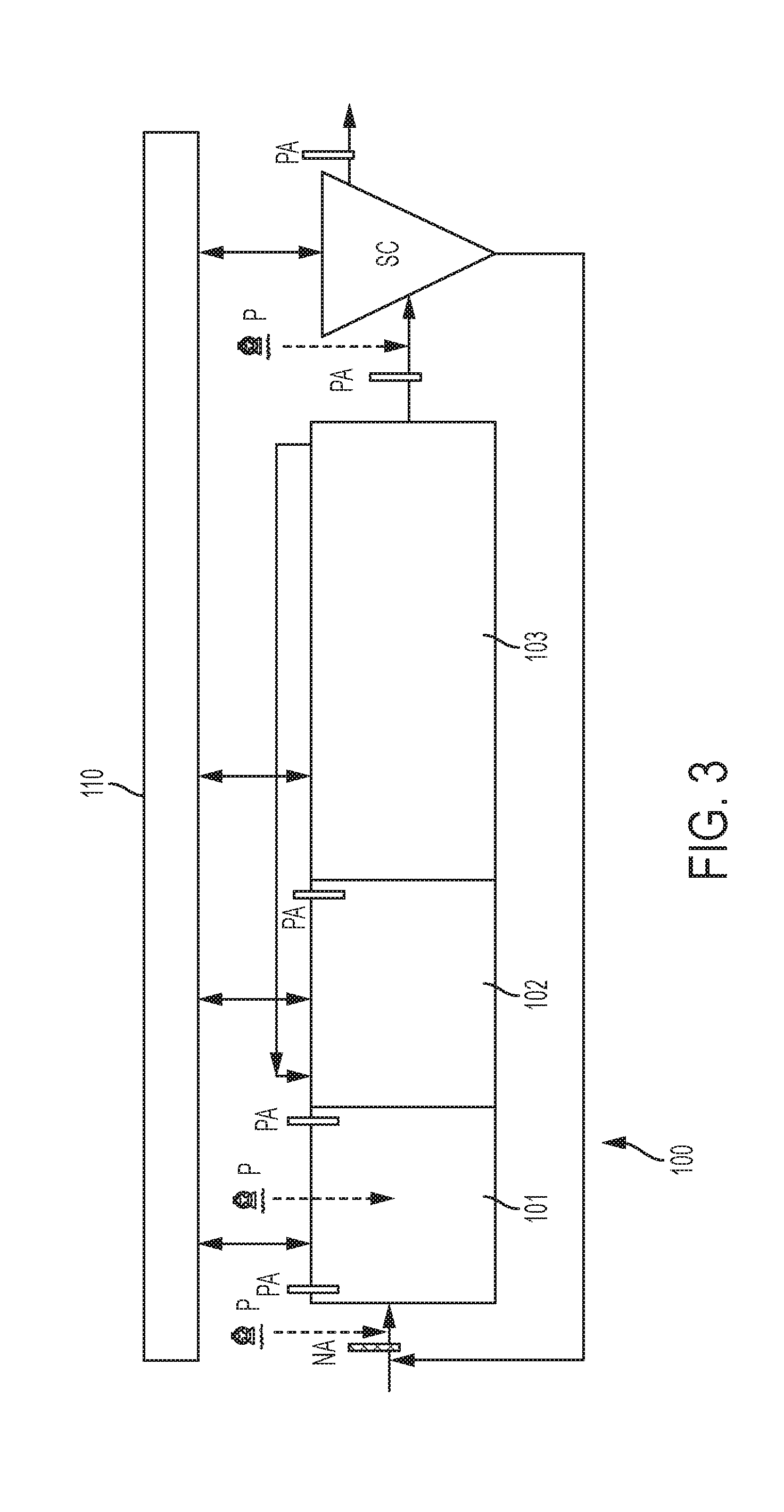
[0175]In this embodiment, which is illustrated in FIG. 3, the central controller 110 is accomplishing denitrification, EBPR and chemical phosphorus removal. The system 100 comprises an anaerobic zone 101, an anoxic zone 102, an aerobic zone 103, and settling tank SC. Nitrogen and phosphorus analyzers, NA and PA, respectively, are used to determine the nitrogen and phosphorus levels at various positions within the system 100. Pumps P dispense a carbon source or a metal compound to the system. The central controller 110 comprises a plurality of control loops (shown generally as double-headed arrows between the central controller and the components of the system) to communicate with the nitrogen and phosphorus analyzers, NA and PA, the pumps P, and other sensors that may be present within the anaerobic zone 101, an anoxic zone 102, an aerobic zone 103, and settling tank SC.
[0176]In the embodiment illustrated in FI...
example 2
Denitrification and Chemical Phosphorus Removal
[0245]Denitrification and chemical phosphorus removal are commonly deployed at wastewater treatment facilities. In some configurations, tertiary denitrification processes, such as a denitrification filter, are utilized to denitrify residual NOX-N prior to discharge. Chemical phosphorus removal often occurs in selectors prior to the tertiary process, such as in a secondary settling tank. Diurnal variability in nitrogen and phosphorus load at wastewater treatment facilities is very common. In order to maintain a healthy and effective biomass in the tertiary denitrification process, the nitrogen to phosphorus ratio has to be balanced. In phosphorus limiting conditions the biomass may become stressed and exhibit extracellular polymeric substances (EPS) that can impact filter operations and compromise denitrification performance. In accordance with the present invention, a central controller may be used to manage both the chemical phosphorus...
example 3
Interrelatedness of EBPR and Denitrification
[0266]In this embodiment, which is illustrated in FIG. 7, the centralized control system 310 removes nitrogen and phosphorus from an activated sludge process known in the art as an A2O Process. This process has three selectors in series (anaerobic 301, anoxic 302, aerobic 303), a nitrate recycle pump from the end of the aerobic selector to the beginning of the anoxic selector and a RAS return to the front end of the anaerobic selector.
[0267]The central control system 310 utilizes a plurality of sensors in the A2O process to accomplish the following. Control loop 1A doses a carbon source to the inlet of the anaerobic zone 301 to remove dissolved oxygen and NOX-N returned in the RAS and dissolved oxygen and NOX-N introduced in the influent flow. Control loop 2A doses the same or a different carbon source, in the same or different location in the anaerobic zone 301, to stimulate phosphorus release. The central controller 310 may also utilize ...
PUM
 Abstract
Description
Claims
Application Information