Check patentability & draft patents in minutes with Patsnap Eureka AI!

Ankle brace

a brace and ankle technology, applied in the field of ankle brace, can solve the problem of not intended summary

Inactive Publication Date: 2017-03-16
OSTERGARD DOAK
View PDF1 Cites 4 Cited by
  • Summary
  • Abstract
  • Description
  • Claims
  • Application Information

AI Technical Summary

Benefits of technology

Enables the ankle to move naturally while preventing injury by resisting motion beyond its normal range, ensuring both flexibility and protection during athletic activities.

Problems solved by technology

Moreover, this Summary is not intended for use as an aid in determining the scope of the claimed subject matter.

Method used


Image

  • Ankle brace
  • Ankle brace
  • Ankle brace

Examples


Embodiment Construction

[0026]Embodiments are described more fully below with reference to the accompanying figures, which form a part hereof and show, by way of illustration, specific exemplary embodiments. These embodiments are disclosed in sufficient detail to enable those skilled in the art to practice the invention. However, embodiments may be implemented in many different forms and should not be construed as being limited to the embodiments set forth herein. The following detailed description is, therefore, not to be taken in a limiting sense in that the scope of the present invention is defined only by the appended claims.

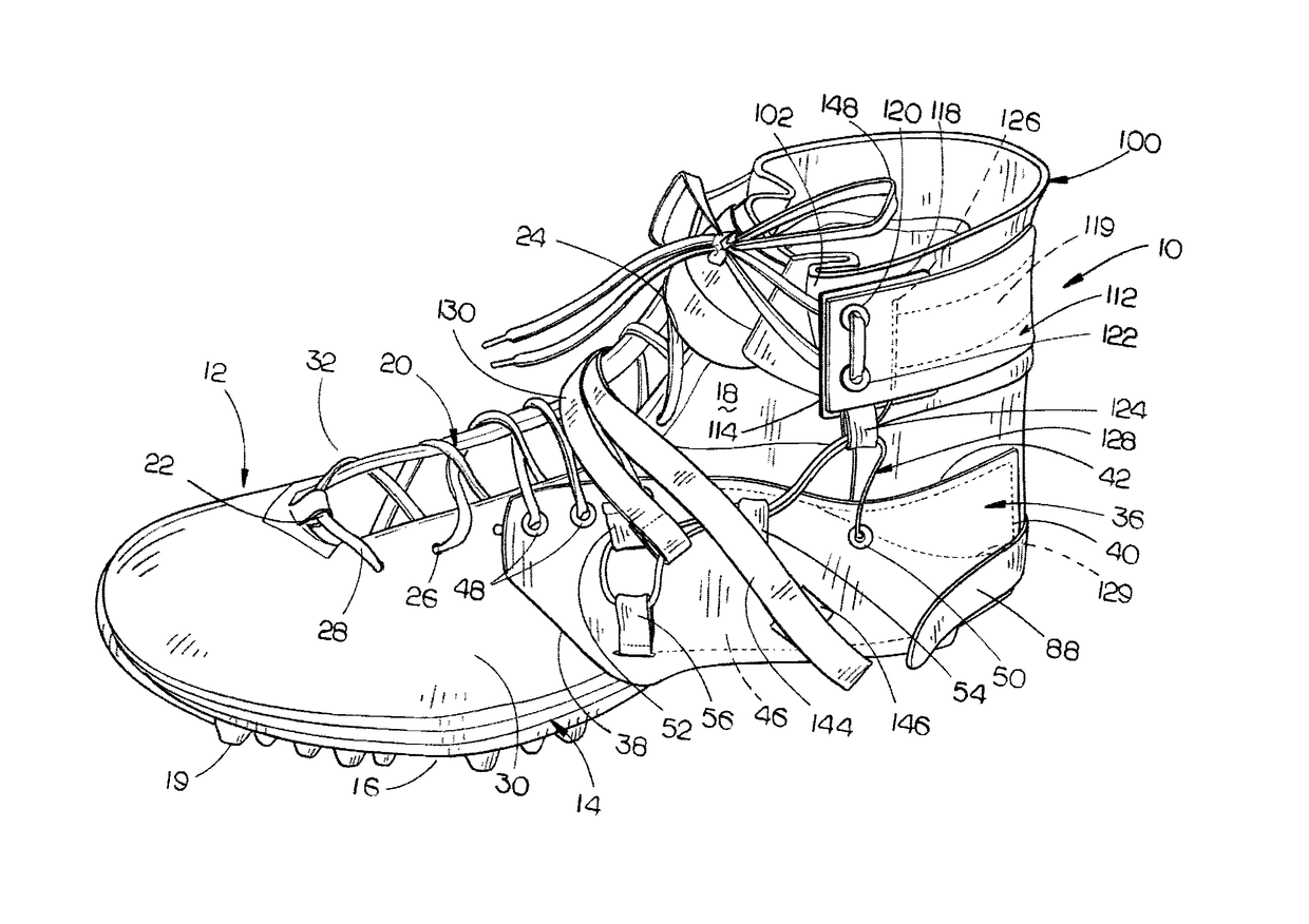
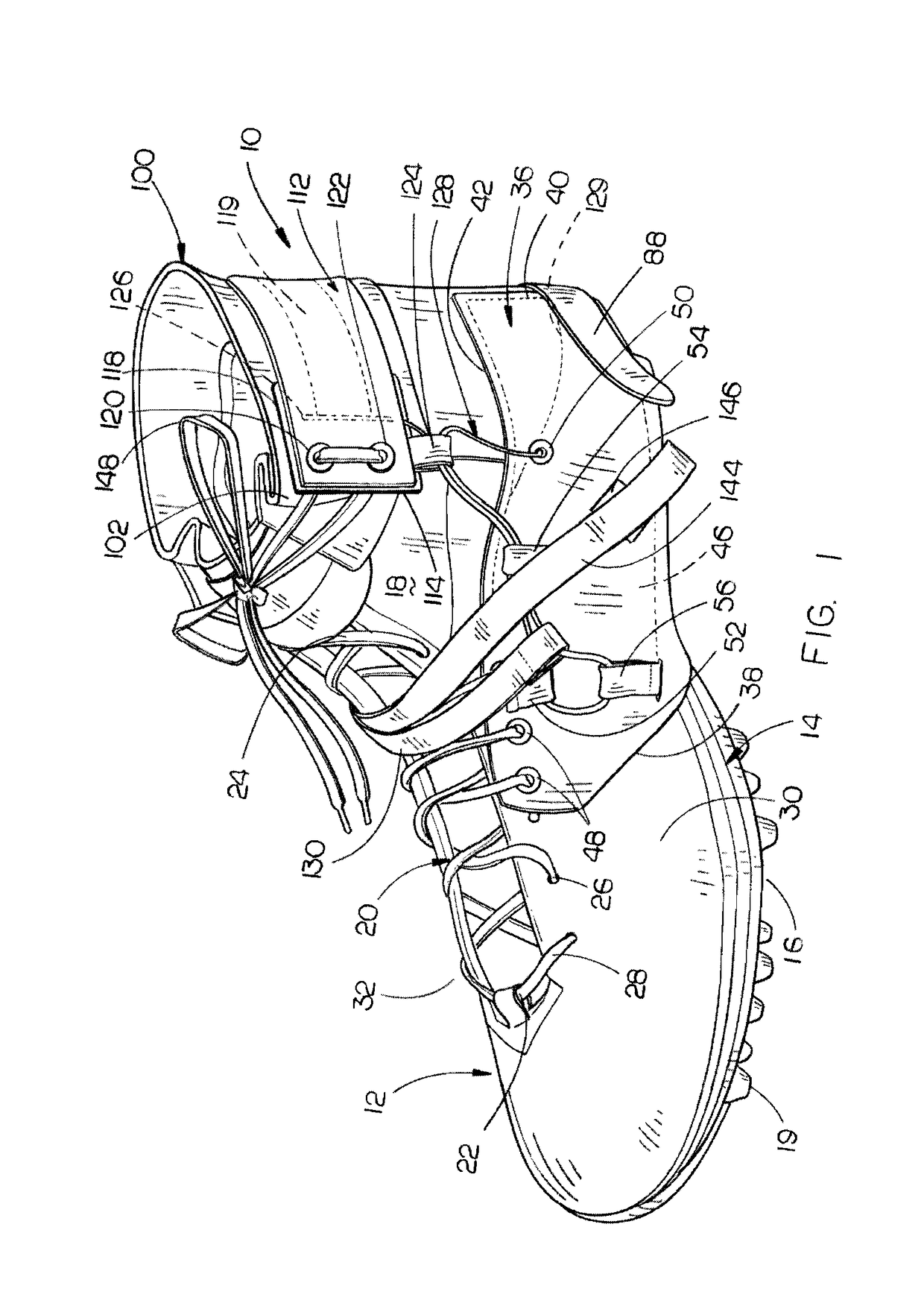
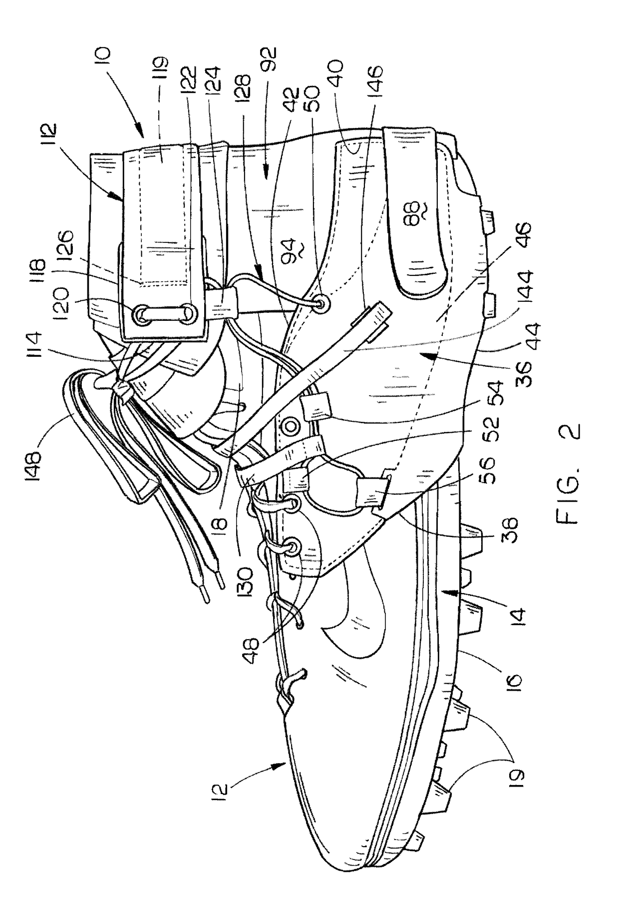
[0027]The ankle brace of this invention is referred to generally by the reference numeral 10. Ankle brace 10 is designed to be attached to an athletic shoe 12 having a sole 14 with an underside 16, and an upper part 18. A plurality of cleats 19 extend downwardly from the underside 16 of sole 14. Upper part 18 has a lacing closure structure 20 having a lower end 22 and an upper end ...


PUM


Abstract

An ankle brace which is positioned on an ankle of a person which incorporates a tensioning structure which permits full range of motion to the ankle joint but which prevents the ankle joint from moving past its normal range of motion to protect the ankle joint.

Description

CROSS REFERENCE TO RELATED APPLICATION[0001]This is a Divisional application of U.S. patent application Ser. No. 13 / 871,094 filed Apr. 26, 2013 entitled ANKLE BRACE which is a Continuation-in-part of U.S. patent application Ser. No. 13 / 134,087, filed May 27, 2011 entitled ANKLE BRACE.BACKGROUND OF THE INVENTION[0002]Field of the Invention[0003]This invention relates to an ankle brace and more particularly to an ankle brace including a tensioning system which functionally stabilizes the ankle as it reaches extreme ranges of motion.[0004]Description of the Related Art[0005]Conventional braces for protecting joints of the body do so by restricting or limiting motion of the joint to which it is applied to prevent a new injury or to protect a pre-existing injury. An ankle joint, just like all the joints in the human body, has a natural range of motion that it can move through without causing damage to itself. As it reaches the end of these ranges, the body has structure such as ligaments...

Claims


Application Information

Patent Timeline
Patent Type & Authority Applications(United States)
IPC IPC(8): A61F5/01A43B5/00A43C15/16A43C5/00A43C1/00
CPCA61F5/0111A43C5/00A43B5/00A43C15/16A43C1/00A43B7/20
Inventor OSTERGARD, DOAK
Owner OSTERGARD DOAK
Features
  • R&D
  • Intellectual Property
  • Life Sciences
  • Materials
  • Tech Scout
  • Unparalleled Data Quality
  • Higher Quality Content
  • 60% Fewer Hallucinations
Learn More