
Charge demand controller device

Active Publication Date: 2018-02-15
RECHARGE VEHICULE ELECTRIQUE INC +1
View PDF6 Cites 8 Cited by
  • Summary
  • Abstract
  • Description
  • Claims
  • Application Information

AI Technical Summary

Benefits of technology

The present invention is a charge demand controller device that can be installed on any existing main power line, even upstream of the electrical control panel. It monitors power consumption and provides power to a charging or EVSE station only when there is available power. The device requires no additional junction boxes and has a relatively easy installation with a short installation time and less hardware. It can also be used as an electrical control panel for the less preferred load of the EVSE. The device allows customization of different parameters, such as the circuit breaker amperage of the main power line, a trip delay duration, a time delay duration before allowing power delivery to the EVSE again, and a maximum charge load amperage to the EVSE. Additionally, the device allows customization of the circuit breaker amperage of the less preferred load.

Problems solved by technology

However, in residential areas, the utility grid is not always well made to easily include the installation of such a charging station like an EVSE or the like.
For example, old electrical installations, and even new ones such as in condominiums and the like, may be limited to the maximum total amperage the electrical control panel can distribute (such as 100 A or less at either 120 or 240 VAC), leaving almost nothing such that such an EVSE cannot be installed, thus requiring the utility providing company to come and upgrade an existing electrical control panel or install a second electrical control panel dedicated to the EVSE charging station, which is relatively expensive.
Alternatively, when the electrical control panel have sufficient amperage and still have the possibility to install additional breakers or the like for directing a dedicated line to a charging station, the location of such panel (distance relative to the car parking zone) render the installation of the charging station relatively expensive again.

Method used


Image

  • Charge demand controller device
  • Charge demand controller device
  • Charge demand controller device

Examples


Embodiment Construction

[0036]With reference to the annexed drawings the preferred embodiment of the present invention will be herein described for indicative purpose and by no means as of limitation.

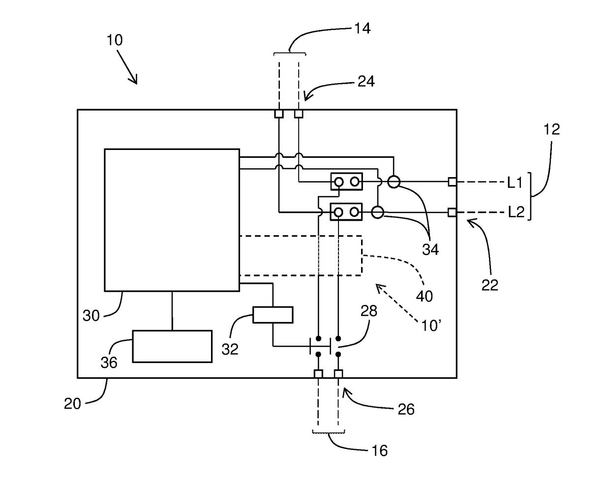
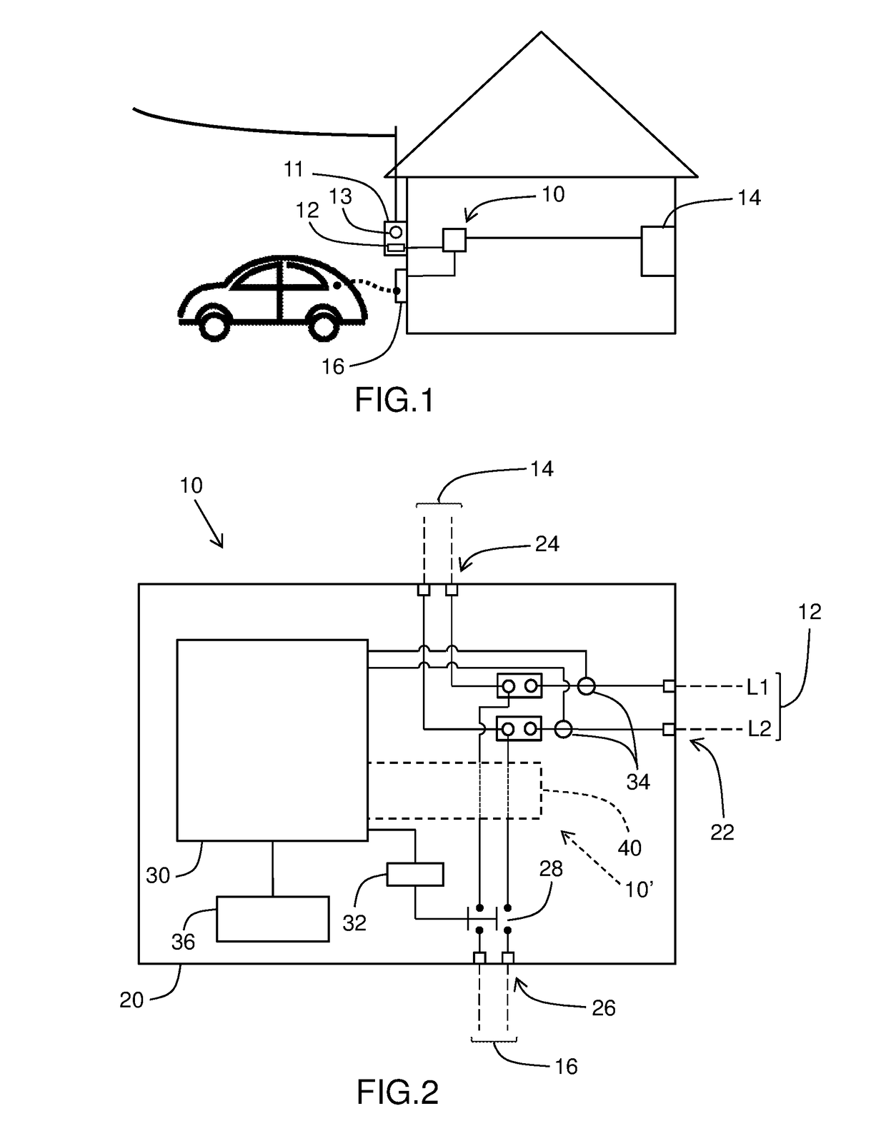
[0037]Referring to FIGS. 1 to 4, there is shown a charge demand controller device 10 in accordance with an embodiment of the present invention for connecting between an electrical control panel 14, or simply electrical panel which includes a conventional fuse box or power source and a switch box, and a main switch 12 typically directly coming from a conventional utility meter 13 and typically found in the utility service box 11, as illustrated in FIG. 1. Although the device 10 can be used to control the charge demand for different external loads, the following description will more specifically refer to the example of a charge demand controller device 10 for which the external load is an electric vehicle supply equipment (EVSE) 16 or the like. The controller device 10 of the present invention, once installed, ...


PUM


Abstract

A charge demand controller device for electric vehicles or the like, preferably for installation with an existing residential electrical control panel, connects between a main switch and the electrical control panel made to operate at a maximum amperage value. The device includes a controller unit that constantly monitors an actual total load current at the input line connector from the main switch, and selectively operates a load switch controlling an electric vehicle supply equipment (EVSE) upon the actual total load current being above or below a trip value being a predetermined safety ratio of the maximum amperage value.

Description

CROSS-REFERENCE TO RELATED APPLICATIONS[0001]This application claims priority of U.S. Provisional Application for Patent No. 62 / 372,779 filed Aug. 9, 2016, the content of which is incorporated herein by reference in its entirety.FIELD OF THE INVENTION[0002]The present invention relates generally to electrical controller devices, and more particularly to charge demand controller device for electric vehicles or the like, preferably for installation with existing residential electrical control panels, or more formally distribution or circuit breaker panels, which each includes a conventional fuse box or power source and a switch box (with conventional power circuit breakers).BACKGROUND OF THE INVENTION[0003]It is well known in the art of to implement stations for the charging of electrical vehicle, usually referred to as an electric vehicle supply equipment (EVSE). However, in residential areas, the utility grid is not always well made to easily include the installation of such a charg...

Claims


Application Information

Patent Timeline
IPC IPC(8): B60L11/18H02J7/00
CPCB60L11/1824H02J7/0068H02J7/0021H02J7/0027B60L11/1861H02J3/14H02J7/02Y02B70/3225Y02T90/14Y04S20/222Y04S30/12B60L53/14B60L53/63B60L53/305H02J2310/60H02J2310/48Y02E60/00Y02T90/16Y02T90/167Y02T10/70Y02T90/12Y02T10/7072Y04S10/126B60L53/30
Inventor CORBEIL, DAVIDMENASSA, CHERIF
Owner RECHARGE VEHICULE ELECTRIQUE INC
Features
  • Generate Ideas
  • Intellectual Property
  • Life Sciences
  • Materials
  • Tech Scout
  • Unparalleled Data Quality
  • Higher Quality Content
  • 60% Fewer Hallucinations
Learn More