
Optical inspection apparatus and method for an extruder

Active Publication Date: 2018-05-10
SACMI COOP MECCANICI IMOLA S C R L
View PDF0 Cites 1 Cited by
  • Summary
  • Abstract
  • Description
  • Claims
  • Application Information

AI Technical Summary

Benefits of technology

This patent describes an optical inspection system for an extruder, which can gather important information on how the extruder operates and identify potential problems with its performance or product quality. The system uses a screw that gradually narrows the space between it and the extruder cylinder, which helps the polymer material move smoothly through the machine. This information can help improve the efficiency and quality of the extrusion process.

Problems solved by technology

These prior art extrusion machines suffer from some problems, however.
One problem is connected with the degrading of the extruder.
For example, prolonged use of the extruder causes wear of the extruder screw (resulting in changes in the extrusion parameters).
It should be noted that substituting the extruder screw is particularly complex and costly.
Another problem is that the product fed out of the extruder (extrudate) might not have the required characteristics.
More specifically, the quality of the extrudate may be impaired (for example, local defects may appear) by unmelted material that is, pellets of polymeric material which have not melted completely) in the outlet zone of the extruder.
These optical inspection systems, however, although they allow checking the polymeric material downstream of the extrusion process, do not tackle the problem of extruder wear and do not provide a robust and reliable answer to the problem of guaranteeing the conformity of the extruded product with specifications.

Method used


Image

  • Optical inspection apparatus and method for an extruder
  • Optical inspection apparatus and method for an extruder
  • Optical inspection apparatus and method for an extruder

Examples


Embodiment Construction

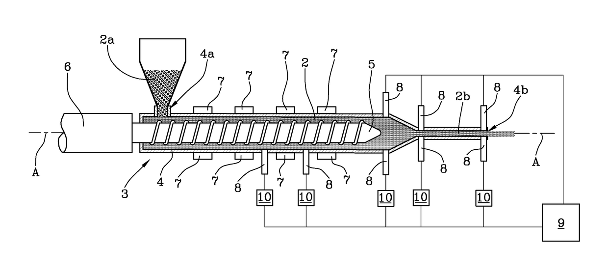
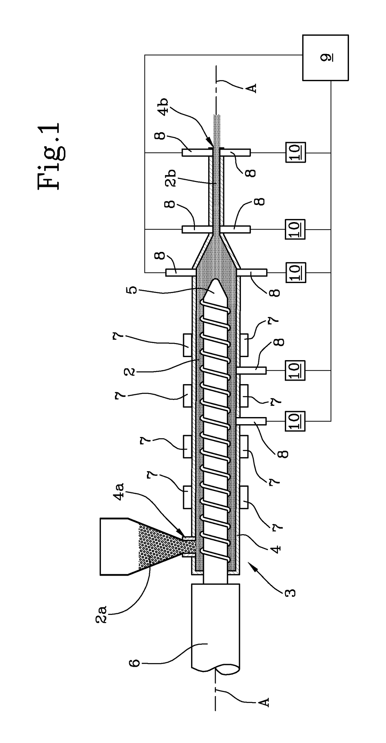
[0077]With reference to the drawings, the numeral 1 denotes an optical inspection apparatus configured to analyse a mass of polymeric material 2 passing through an extruder 3.

[0078]The extruder 3 comprises a hollow extrusion cylinder 4 extending elongately in a longitudinal direction. The extrusion cylinder 4 has an inlet 4a, preferably located at a first end, for receiving pellets 2a of polymeric material 2. The extrusion cylinder 4 has an outlet 4b, preferably located at a second end, for expelling melted polymeric material 2b.

[0079]The extruder 3 has an extruder screw 5, preferably connected to a motor 6, configured to drive it in rotation about a longitudinal axis A inside the extrusion cylinder 4 to move the polymeric material 2 from the inlet 4a to the outlet 4b.

[0080]The extruder 3 also comprises a plurality of heaters 7 coupled to the extrusion cylinder 4 to exchange heat therewith. In an example embodiment, the heaters 7 comprise electrical resistors and / or heat exchanger...


PUM

PropertyMeasurementUnit
Nanoscale particle sizeaaaaaaaaaa
Wavelengthaaaaaaaaaa

Abstract

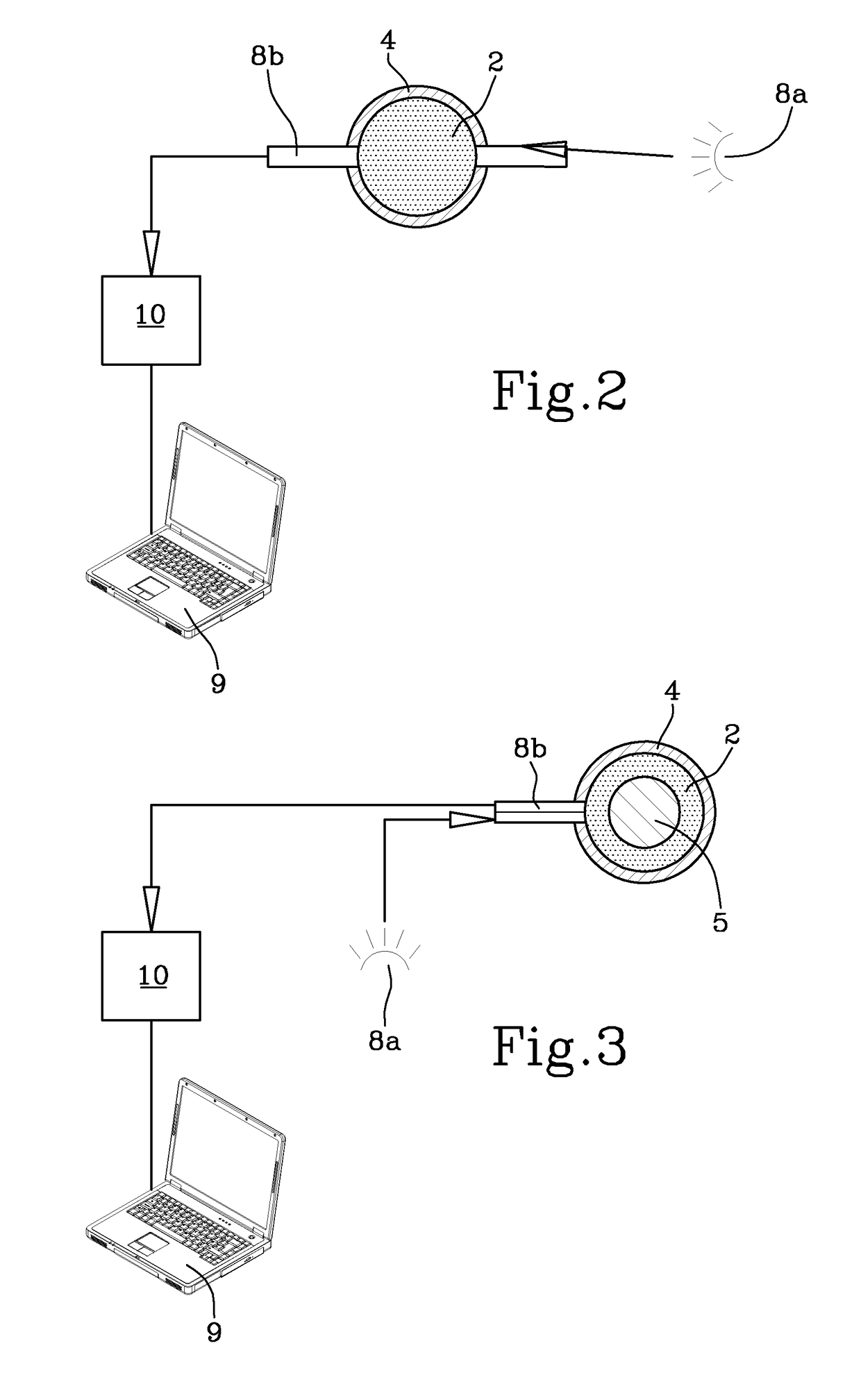
An apparatus (1) for optical inspection of a mass of polymeric material (2) passing through an extruder (3) having a hollow extrusion cylinder (4) extending elongately in a longitudinal direction comprises an optical sensor (8) which can be operatively coupled to the extrusion cylinder (4) and having an infrared light emitter (8a) and a receiver (8b) configured to measure a measurement parameter representing an optical property of the polymeric material (2) inside the extrusion cylinder (4) and is characterized in that it comprises a plurality of the optical sensors (8) which can be operatively coupled to the extrusion cylinder (4) in a plurality of measurement sites located in succession and spaced from each other along the longitudinal direction and a processor (9) programmed to acquire a plurality of measurement signals containing the measurement parameters measured by the corresponding optical sensors (8) and programmed to process the plurality of measurement signals in order to calculate a corresponding plurality of values of a control parameter indicating a physical state of the polymeric material (2) as a function of a longitudinal position.

Description

TECHNICAL FIELD[0001]This invention relates to an optical inspection apparatus and method for an extruder. The invention also relates to an extruder.[0002]The invention addresses the plastics industry. More specifically, it is applicable in the field of extrusion of thermoplastic polymeric materials. Thermoplastic polymers soften or melt when heated and return to the solid state when cool.BACKGROUND ART[0003]Generally speaking, extrusion machines (or extruders) allow obtaining extrudates, that is, objects made of plastic material (typically constant in cross section) of predetermined length, starting from pellets (or granules, for example, small cylinders or discs between 1 and 5 mm in diameter) made of a polymer or polymeric mixture and used as raw material to make the plastic objects.[0004]Extrusion machines are also used in the plastic moulding industry, where an injection mould is located downstream of an extrusion machine to receive melted polymeric material and make a plastic ...

Claims


Application Information

Patent Timeline
IPC IPC(8): G01N21/359B29C47/92B29C47/82B29C48/92
CPCG01N21/359B29C47/92B29C47/822B29C2947/92247B29C2947/922B29C2947/9238B29C2947/92409B29C2947/92704G01N2021/3595B29C48/92B29C48/832B29C2948/92247B29C2948/92361B29C2948/92876B29C2948/9219B29C2948/92714B29C2948/92219B29C2948/922B29C2948/92685B29C2948/92695B29C2948/9238B29C2948/92409B29C2948/92704
Inventor BOSI, GILDO
Owner SACMI COOP MECCANICI IMOLA S C R L
Learn More