Check patentability & draft patents in minutes with Patsnap Eureka AI!

Distributed database system and distributed data processing method

a database system and data processing technology, applied in the field of data base system and data processing method, can solve the problems of high cost of the system, difficulty in solving the above-described problem of load concentration, and the possibility of lowering efficiency, so as to achieve efficient data storage, simple data rearrangement, and the effect of distributing the load for a search process

Inactive Publication Date: 2018-07-19
KK TOSHIBA
View PDF5 Cites 1 Cited by
  • Summary
  • Abstract
  • Description
  • Claims
  • Application Information

AI Technical Summary

Benefits of technology

The present invention provides a database system and data processing method that can efficiently store and retrieve data. It also effectively distributes the load for search processes and allows for easy rearrangement of data based on simple key information.

Problems solved by technology

Meanwhile, in the conventional technology, the central server apparatus side needs to include a large capacity storage unit (for example, a magnetic hard disk device, a semiconductor memory, or the like) for storing a large amount of data, and there are cases in which the system incurs a high cost.
However, in the conventional technology, when a system architecture in which data is centrally stored in the central server apparatus is employed, a storage unit of such a terminal device and an intermediate device are not used, and there is room for improvement.
In the conventional technology, since data is centrally stored in the central server apparatus, when collected data is searched (execution of a query), the load of the process is concentrated on the central server apparatus, and there is a possibility of lowered efficiency.
However, even in such a system, data is centrally stored in a central server apparatus, and it is difficult to solve the above-described problem of load concentration.
However, a complicated process is necessary for the determination of distributed arrangement on the basis of access distribution, and there is a problem in that the management becomes complex.

Method used


Image

  • Distributed database system and distributed data processing method
  • Distributed database system and distributed data processing method
  • Distributed database system and distributed data processing method

Examples


first embodiment

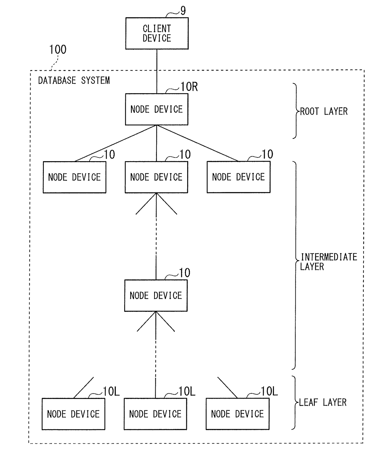
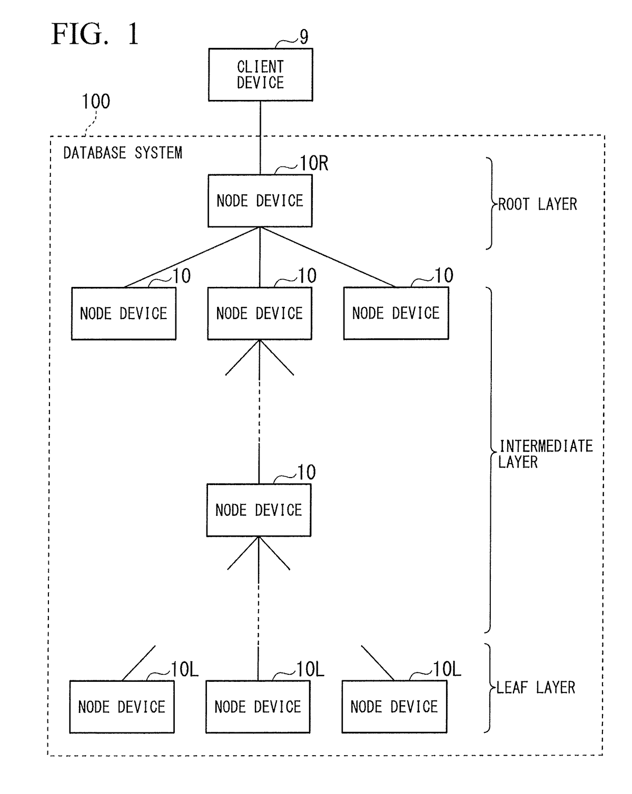
[0037]FIG. 1 is a configuration diagram illustrating a schematic configuration of a database system according to this embodiment. As illustrated in the drawing, the database system 100 is configured to include a plurality of node devices 10 arranged in a hierarchical structure. In other words, the database system 100 is formed by connecting a plurality of node devices in a parent-child relation having a hierarchical structure. Such node devices 10 are arranged in a tree structure pattern. In other words, each node device 10 is connected to no parent node or one parent node and is connected to no child node or one or more child nodes. In the drawing, a node device 10 arranged on the upper side is in a parent direction, and a node device 10 arranged on the lower side is in a child direction. In such a hierarchical structure of the node devices 10, particularly, a node device of the highest rank having no parent is a root node device. A reference numeral 10R is assigned to the root nod...

second embodiment

[0170]Next, a second embodiment will be described. Hereinafter, description of items common to the embodiment described above will not be presented, and items that are distinctive in this embodiment will be focused in the description.

[0171]The configuration of data stored in the database system according to the first embodiment is as illustrated in FIG. 3. On the other hand, a database system 101 according to this embodiment stores a plurality of series (time series) of data.

[0172]FIG. 14 is a schematic diagram illustrating the basic structure of data stored by the database system 101 according to this embodiment. A data storing unit 20 of each node device 10 included in the database system 101 stores data having the structure illustrated in the drawing. As illustrated in the drawing, the database system 101 stores and manages time (order information) and a data content in association with each other. As a feature of this embodiment, the database system 101 manages data of a plurali...

third embodiment

[0190]Next, a third embodiment will be described. Hereinafter, description of items common to each embodiment described above will not be presented, and items that are distinctive in this embodiment will be focused in the description. As a feature of a database system according to this embodiment, the node device 10 does not necessarily need to be connected in a tree structure pattern.

[0191]FIG. 18 is a schematic diagram illustrating an example of the configuration of the database system 102 according to this embodiment. As illustrated in the drawing, also in this embodiment, the database system 102 is configured by connecting a plurality of node devices 10. Between the node devices, a relation of a parent node and a child node is defined. In the drawing, the source side of a directional arrow is a parent node, and the destination side is a child node. In the database system 102, for example, a node device 10-8 includes two parents of node devices 10-5 and 10-6. In this way, in the ...


PUM


Abstract

A database system is formed by connecting node devices in parent-child relations. Each of the node devices includes a data storing unit, a saving rule storing unit, a storage processing unit, and an inquiry processing unit. The saving rule storing unit stores a saving rule used for saving data stored in the data storing unit to a parent node device in a case in which its own node device is not a parent of a highest rank and deleting the data in a case in which its own node device is the parent of the highest rank. The storage processing unit writes data and saves data to be saved from the data storing unit into a parent node in an order represented by order information associated with the data or deletes data to be deleted by referring to the saving rule.

Description

BACKGROUND OF THE INVENTIONField of the Invention[0001]Embodiments of the present invention relate to a database system and a data processing method.Description of Related Art[0002]According to the wide use of IoT devices, data generated at various places under various situations is used through networks more frequently. In a conventional technology, data generated by IoT devices and the like is collected in a central server apparatus through a network and is stored in a database system of the central server apparatus. Massive data stored in a database system of a central server apparatus is searched and used by a user when necessary.[0003]Meanwhile, in the conventional technology, the central server apparatus side needs to include a large capacity storage unit (for example, a magnetic hard disk device, a semiconductor memory, or the like) for storing a large amount of data, and there are cases in which the system incurs a high cost.[0004]An IoT device and a device relaying the IoT ...

Claims


Application Information

Patent Timeline
IPC IPC(8): G06F17/30
CPCG06F17/30545G06F17/30283G06F17/30327G06F16/2246G06F16/2471G06F16/27
Inventor KATAYAMA, TAIGAKANEMATSU, MOTOTAKAHIROSE, SHIGEO
Owner KK TOSHIBA
Features
  • R&D
  • Intellectual Property
  • Life Sciences
  • Materials
  • Tech Scout
  • Unparalleled Data Quality
  • Higher Quality Content
  • 60% Fewer Hallucinations
Learn More