Trigger circuit

Inactive Publication Date: 2018-12-06
PIXART IMAGING INC
View PDF5 Cites 1 Cited by
  • Summary
  • Abstract
  • Description
  • Claims
  • Application Information

AI Technical Summary

Benefits of technology

The present invention provides a design for a trigger switch that saves hardware costs, reduces power consumption, and decreases the occurrence of judgment errors by only slightly increasing the complexity of the trigger circuit. This is achieved by not adding a new impedance device when adding another trigger.

Problems solved by technology

However, in recent years, electronic products are made to be more tiny and delicate.
In these electronic products with limited space, the complexity of the circuit design often increases with the number of functions thereof.
That is, adding more triggers (i.e., more new resistors) will lead to a more complex computation to determine more trigger threshold intervals.
Therefore, the trigger circuit will require a larger area and bring about a larger power consumption accordingly.
This also makes the trigger threshold intervals become smaller, and makes judgment errors occur more frequently.

Method used


Image

  • Trigger circuit
  • Trigger circuit
  • Trigger circuit

Examples


Embodiment Construction

[0024]Reference will now be made in detail to the exemplary embodiment of the present disclosure, examples of which are illustrated in the accompanying drawings. Wherever possible, the same reference numbers are used in the drawings and the description to refer to the same or like parts.

[Trigger Switch Connected with a Constant Voltage Source]

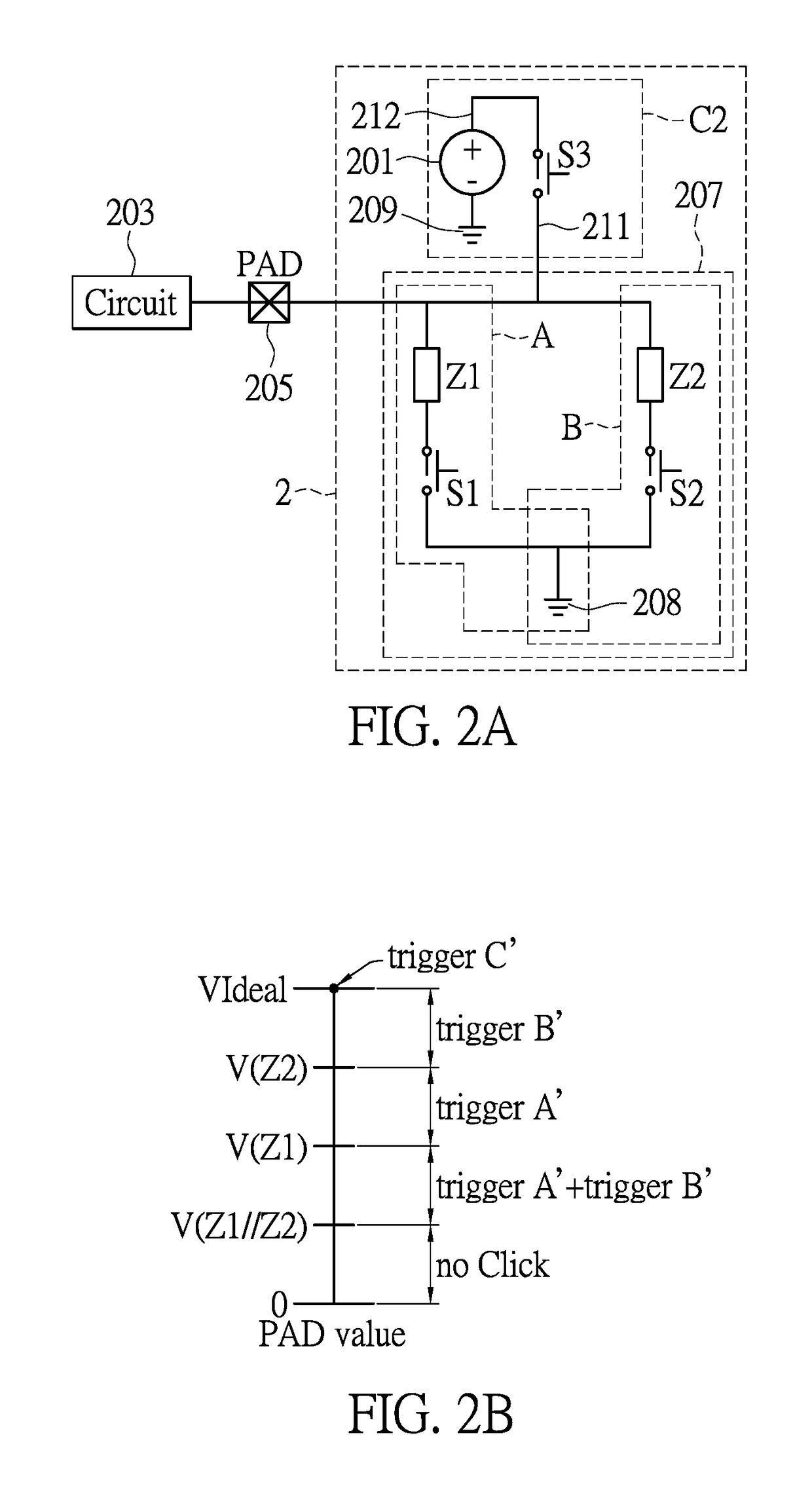
[0025]First of all, referring to FIG. 2A, FIG. 2A shows an embodiment of a pin-shared trigger circuit of the present disclosure. Via a trigger C′, an additional trigger can be disposed in the present disclosure without having to add a new impedance device Z3, thereby saving hardware costs while only slightly increasing the complexity of the circuits.

[0026]In practice, a pin-shared trigger circuit will have a plurality of triggers (e.g., buttons, virtual buttons or any type of switch) corresponding to an electronic apparatus (e.g., a mouse, a keyboard or a touch panel apparatus).

[0027]In FIG. 2A, a trigger circuit 2 of the exemplary embodiment o...


PUM


Abstract

The present disclosure illustrates a trigger circuit applied to an electronic apparatus having a plurality of triggers, which includes a trigger switch and a trigger network. The trigger switch, corresponding to one of the plurality of triggers, has a first end and a second end, in which the first end of the trigger switch is connected with a pad, and the second end of the trigger switch is connected with a voltage source having a first voltage value. Further, the trigger network, corresponding to a rest of the plurality of triggers, has at least one trigger sub-circuit electrically connected with the pad, in which the trigger network has an impedance value. When the trigger switch is triggered, due to an impedance value of the trigger network, the first voltage value will be detected at the pad.

Description

BACKGROUND1. Technical Field[0001]The present disclosure is related to a trigger circuit, and more particularly to a pin-shared trigger circuit.2. Description of Related Art[0002]In modern technology, electronic products are all formed with circuits. When a circuit state needs to be changed or a signal needs to be sent, a trigger is usually used. Conventional simple circuit designs are intuitive, with the number of triggers often corresponding to the number of functions provided.[0003]However, in recent years, electronic products are made to be more tiny and delicate. In these electronic products with limited space, the complexity of the circuit design often increases with the number of functions thereof. Therefore, a pin-shared conception was developed to alleviate the foregoing issue. In brief, when a plurality of triggers sharing one pin are triggered in combination, a corresponding specific value will be detected via a detecting circuit at a pad at the position of the pin, and t...

Claims


Application Information

Patent Timeline
IPC IPC(8): H03K17/967H01H13/70H03K17/96G06F3/033
CPCH03K17/967G06F3/033H03K17/96H01H13/70G06F3/03543G06F3/038G06F3/0202G06F3/023G06F3/0383G06G7/04G06F3/0362
Inventor CHEN, PENG-SHENGCHIU, JUI-TELIU, HAN-CHI
Owner PIXART IMAGING INC
Why Eureka
Try Eureka