Check patentability & draft patents in minutes with Patsnap Eureka AI!

Wireless power transmitter and wireless power receiver

a wireless power transmitter and receiver technology, applied in cross-talk/noise/interference reduction, printed circuit aspects, transportation and packaging, etc., can solve the problems of easy contamination by foreign substances, battery charging may battery charging may also not be correctly performed, etc., to reduce emi, reduce weight and volume of an entire device, the effect of reducing emi

Active Publication Date: 2018-12-13
SAMSUNG ELECTRONICS CO LTD
View PDF0 Cites 0 Cited by
  • Summary
  • Abstract
  • Description
  • Claims
  • Application Information

AI Technical Summary

Benefits of technology

This patent describes a way to reduce EMI (electromagnetic interference) in wireless power transmitters and receivers. By separating the layers that carry alternating current and direct current, the method eliminates the need for a separate component to reduce EMI, which can save money and make the device smaller and lighter. This is a big technical improvement without adding any extra cost or complexity.

Problems solved by technology

However, in such a contact-type charging scheme, the contact terminals protrude outwardly, and thus are easily contaminated by foreign substances.
As a result, battery charging may not be correctly performed.
Further, the battery charging may also not be correctly performed in a case where the contact terminal is exposed to moisture.

Method used


Image

  • Wireless power transmitter and wireless power receiver
  • Wireless power transmitter and wireless power receiver
  • Wireless power transmitter and wireless power receiver

Examples


Embodiment Construction

Technical Problem

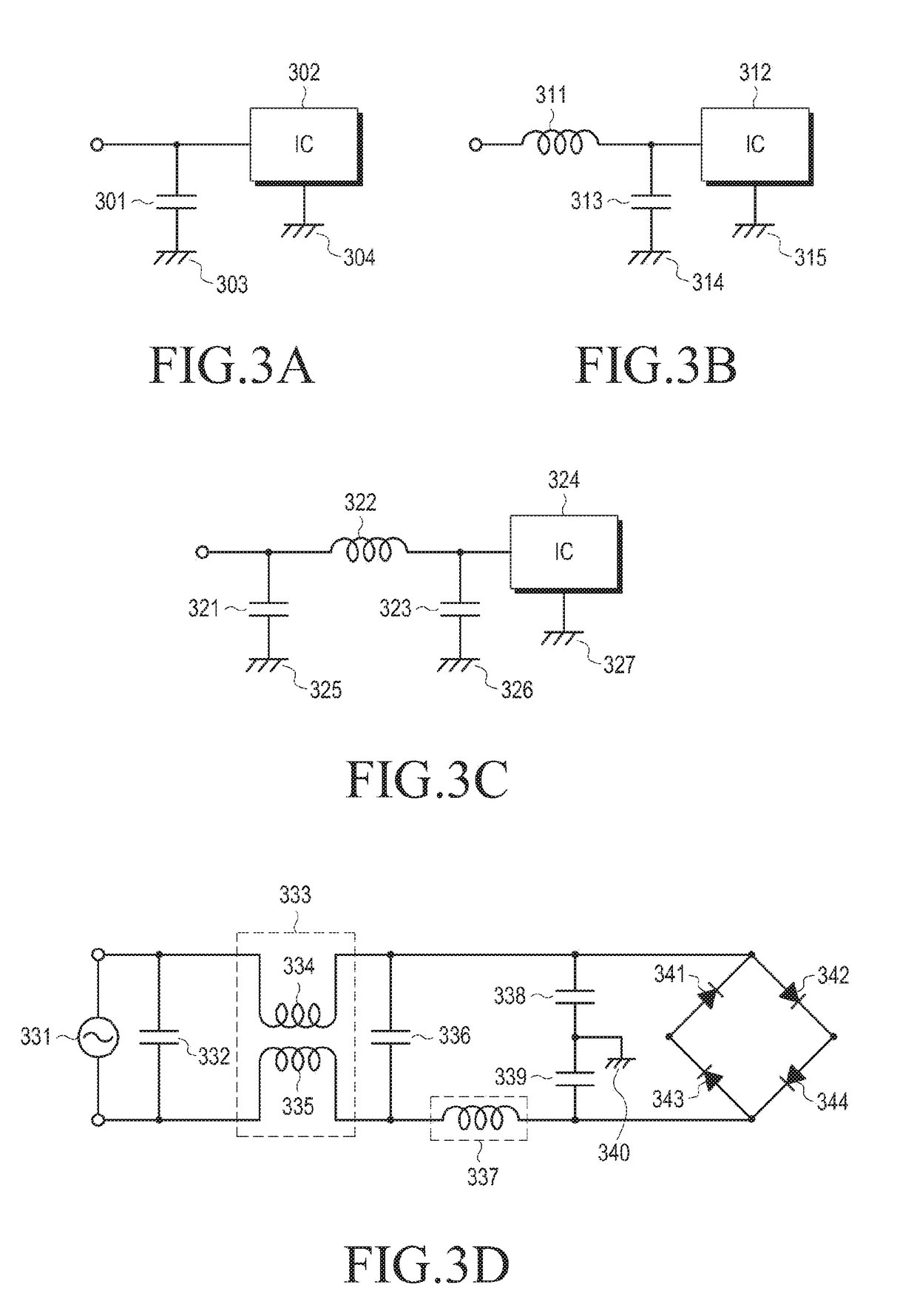
[0010]Conventional wireless power transmitters and wireless power receivers can cause electro-magnetic interference (EMI). The EMI can signify that an electromagnetic wave directly radiated or conducted from an electronic device affects a function of another electronic device. In order to reduce the EMI, a conventional wireless power receiver includes an impedance matching circuit, a filter, and a shielding element. However, those elements added to the conventional wireless power receiver increase the entire volume and weight of the wireless power receiver and thus makes it difficult to reduce a size of the wireless power receiver. Particularly, since filters have large volume and capacity, it is difficult to apply a filter to a small-sized product, such as a mobile device. In addition, even if a filter is adopted, EMI is not completely reduced. Further, inclusion of various passive elements causes a problem of increased cost.

[0011]Various embodiments of the present...


PUM


Abstract

A wireless power receiver for wirelessly receiving power from a wireless power transmitter comprises: a power reception circuit receiving electromagnetic waves emitted from the wireless power receiver so as to output power having an alternating current waveform; a rectifier for rectifying the power, having an AC waveform, outputted from the power reception circuit into power having a direct current waveform; a DC / DC converter for converting, into a voltage of a preset level, a voltage of the power having a direct current waveform, the power being rectified by the rectifier; a charger for charging a battery by using the power having a DC waveform, converted from the DC / DC converter; an alternating current ground connected to the power reception circuit and / or the rectifier so as to receive at least a portion of the power having an alternating current waveform; and a direct current ground connected to the DC / DC converter and / or the charger so as to receive at least a portion of the power having a direct current waveform, wherein the alternating current ground and the direct current ground can be disposed on different PCB layers, respectively.

Description

TECHNICAL FIELD[0001]The present disclosure relates to a wireless power transmitter and a wireless power receiver and, specifically, relates to a wireless power transmitter configured to wirelessly transmit power to a wireless power receiver and a wireless power receiver configured to wirelessly receive power from a wireless power transmitter.BACKGROUND ART[0002]Mobile terminals such as a mobile phone, a Personal Digital Assistant (PDA), and the like are driven with rechargeable batteries due to their nature, and the battery of the mobile terminal is charged through supplied electric energy by using a separate charging apparatus. Typically, the charging device and the battery have separate contact terminals at an exterior thereof, respectively, and are electrically connected with each other by contacting the contact terminals.[0003]However, in such a contact-type charging scheme, the contact terminals protrude outwardly, and thus are easily contaminated by foreign substances. As a r...

Claims


Application Information

Patent Timeline
Patent Type & Authority Applications(United States)
IPC IPC(8): H02J7/02H02J50/40H02J50/12
CPCH02J7/025H02J50/40H02J50/12H02J50/70H05K1/0218H05K1/0224H05K3/46H05K2201/0723H05K2201/09354H05K2201/09972H02J7/0013H02J50/10
Inventor LEE, CHONG-MINKIM, YU-SUCHUNG, HYUNG-KOOHAN, HYO-SEOK
Owner SAMSUNG ELECTRONICS CO LTD
Features
  • R&D
  • Intellectual Property
  • Life Sciences
  • Materials
  • Tech Scout
  • Unparalleled Data Quality
  • Higher Quality Content
  • 60% Fewer Hallucinations
Learn More