Heat exchanging apparatus, cooling apparatus, and projector
a technology of heat exchange apparatus and cooling apparatus, which is applied in the direction of lighting and heating apparatus, stationary conduit assemblies, instruments, etc., can solve the problem that liquid refrigerant cannot be sufficiently cooled, and achieve the effect of efficient cooling of liquid refrigeran
- Summary
- Abstract
- Description
- Claims
- Application Information
AI Technical Summary
Benefits of technology
Problems solved by technology
Method used
Image

Examples
first embodiment
[0050]A first embodiment of the invention will be described below with reference to the drawings
Exterior Configuration of Projector
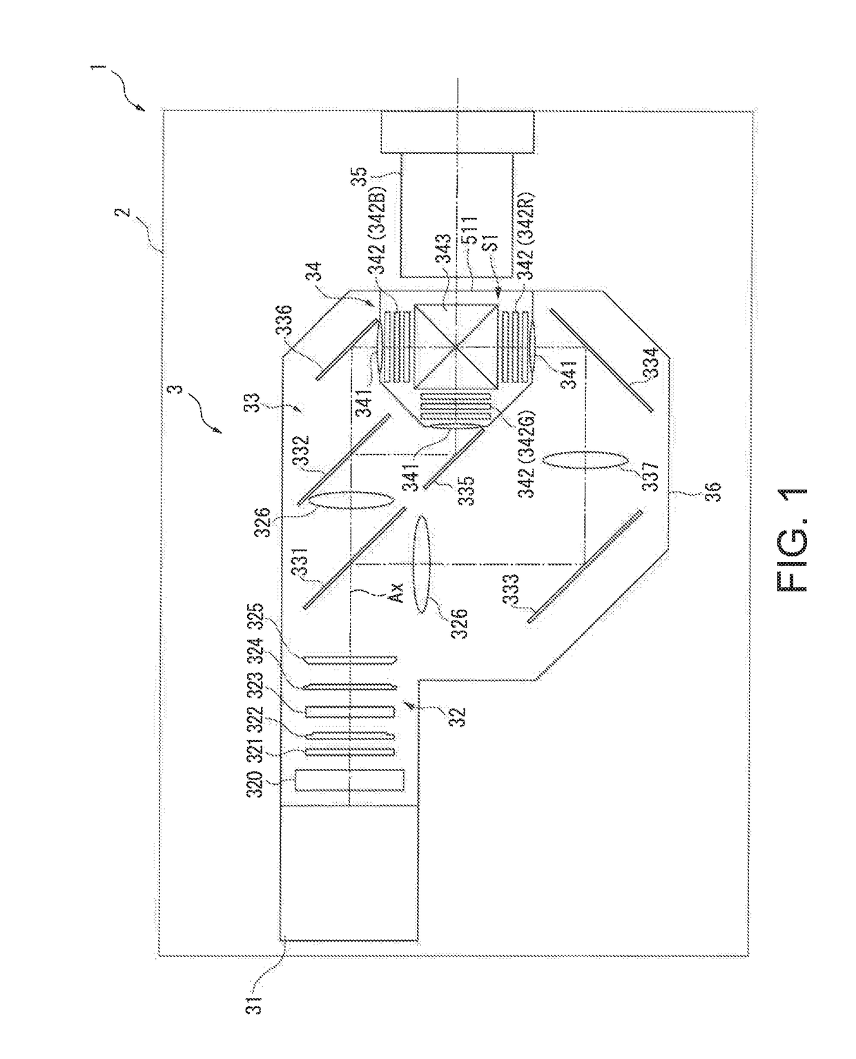
[0051]FIG. 1 is a diagrammatic view showing the configuration of a projector 1 according to the present embodiment.
[0052]The projector 1 according to the present embodiment is a projection-type display apparatus that modulates light outputted from a light source apparatus 31, which will be described later, to form and project an image according to image information. The projector 1 includes a roughly rectangular porallelepiped exterior enclosure 2 and an image projection apparatus 3 disposed in the exterior enclosure 2, as shown in FIG. 1.
[0053]The thus configured projector 1 is partly characterized by the configuration of a heat exchanging apparatus that transfers heat of a liquid refrigerant having cooled a cooling target to another refrigerant to cool the liquid refrigerant. The heat exchanging apparatus will be described later in detail.
[0054]The con...
second embodiment
[0165]A second embodiment of the invention will next be described.
[0166]A projector according to the present embodiment has the same configuration as that of the projector 1 described above but differs therefrom in terms of the configuration of the heat exchanging apparatus provided in the third circulation channel 53. In the following description, the same portions or roughly the same portions as those having been already described have the same reference characters and will not be described.
[0167]FIG. 6 is a diagrammatic view showing the internal configuration of a heat exchanging apparatus 6A provided in the projector according to the present embodiment.
[0168]The projector according to the present embodiment has the same configuration and function as those of the projector 1 described above except that the heat exchanging apparatus 6 in the first embodiment is replaced with the heat exchanging apparatus 6A.
[0169]The heat exchanging apparatus 6A forms the third circulation channel...
third embodiment
[0179]A third embodiment of the invention will next be described.
[0180]A projector according to the present embodiment has the same configuration as that of the projector 1 described above but differs therefrom in terms of the configuration of the heat exchanging apparatus provided in the third circulation channel 53. In the following description, the same portions or roughly the same portions as those having been already described have the same reference characters and will not be described.
[0181]FIG. 7 is a diagrammatic view showing the configuration of a heat exchanging apparatus 7 provided in the projector according to the present embodiment.
[0182]The projector according to the present embodiment has the same configuration and function as those of the projector 1 described above except that the heat exchanging apparatus 6 in the first embodiment is replaced with the heat exchanging apparatus 7.
[0183]The heat exchanging apparatus 7 forms the third circulation channel 53, is conne...
PUM
 Abstract
Description
Claims
Application Information
 - R&D
- Intellectual Property
- Life Sciences
- Materials
- Tech Scout
- Unparalleled Data Quality
- Higher Quality Content
- 60% Fewer Hallucinations
Browse by: Latest US Patents, China's latest patents, Technical Efficacy Thesaurus, Application Domain, Technology Topic, Popular Technical Reports.
© 2025 PatSnap. All rights reserved.Legal|Privacy policy|Modern Slavery Act Transparency Statement|Sitemap|About US| Contact US: help@patsnap.com