Supercharge Your Innovation With Domain-Expert AI Agents!

Photon generator

a generator and photon technology, applied in the field ofquantum information processing, can solve the problems of 50% loss inherent in critical coupling, destructive interference, and no light can leave the resonator

Active Publication Date: 2019-05-16
THE UNITED STATES OF AMERICA AS REPRESETNED BY THE SEC OF THE AIR FORCE
View PDF5 Cites 0 Cited by
  • Summary
  • Abstract
  • Description
  • Claims
  • Application Information

AI Technical Summary

Benefits of technology

[0013]In a fundamental embodiment of the present invention, a frequency selective optical coupling device, comprises an annular optical channel, a first linear optical channel having a first input and a first output where the first linear optical channel is substantially tangential to the annular optical channel at a first point and a second point, a second linear optical channel having a second input and a second output, where the second linear optical channel is substantially tangential to the annular optical channel at a third point and a fourth point; and a predeterminable relative phase delay between the first and the second linear optical channels so as to cause a variance in an amount of light traversing the first and the second linear optical channels as a function of the frequency of the light.
[0014]In the preferred embodiment of the present invention, a photon generator device comprises an annular optical channel disposed in a chip, a first linear optical channel disposed in the chip, where the channel has a first input and a first output and where the first input and a first output are in common with each other and with an input to the chip, where the first linear optical channel is substantially tangential to the annular optical channel at a first point and a second point, and where a second linear optical channel is disposed in the chip with the second linear optical channel having a second input and a second output, where the second linear optical channel is substantially tangential to the annular optical channel at a third point and a fourth point, a first predeterminable relative phase delay between the first and the second linear optical channels so as to cause a variance in an amount of light traversing the first and the second linear optical channels as a function of the frequency of said light, and a second predeterminable relative phase delay between the second input and the second output, a photon detector sampling each of the second input and the second output, and a third output of the chip in common with the second input, a fourth output of the chip in common with the second output, and an electronic control subsystem in operative communication with the chip for facilitating the predeterminable relative phase delays and the photon detection.

Problems solved by technology

One of the fundamental issues with ring resonators is their inherent 50% loss when critically coupled, regardless of operation in a single bus or double bus configuration.
When light after a full round trip around the ring is of equal intensity and opposite phase to light that is reflecting into the ring, there is a destructive interference and no light can leave the resonator.
The underlying issue of single and double bus ring resonators is that they do not have wavelength discriminating couplers.

Method used


Image

  • Photon generator
  • Photon generator
  • Photon generator

Examples


Embodiment Construction

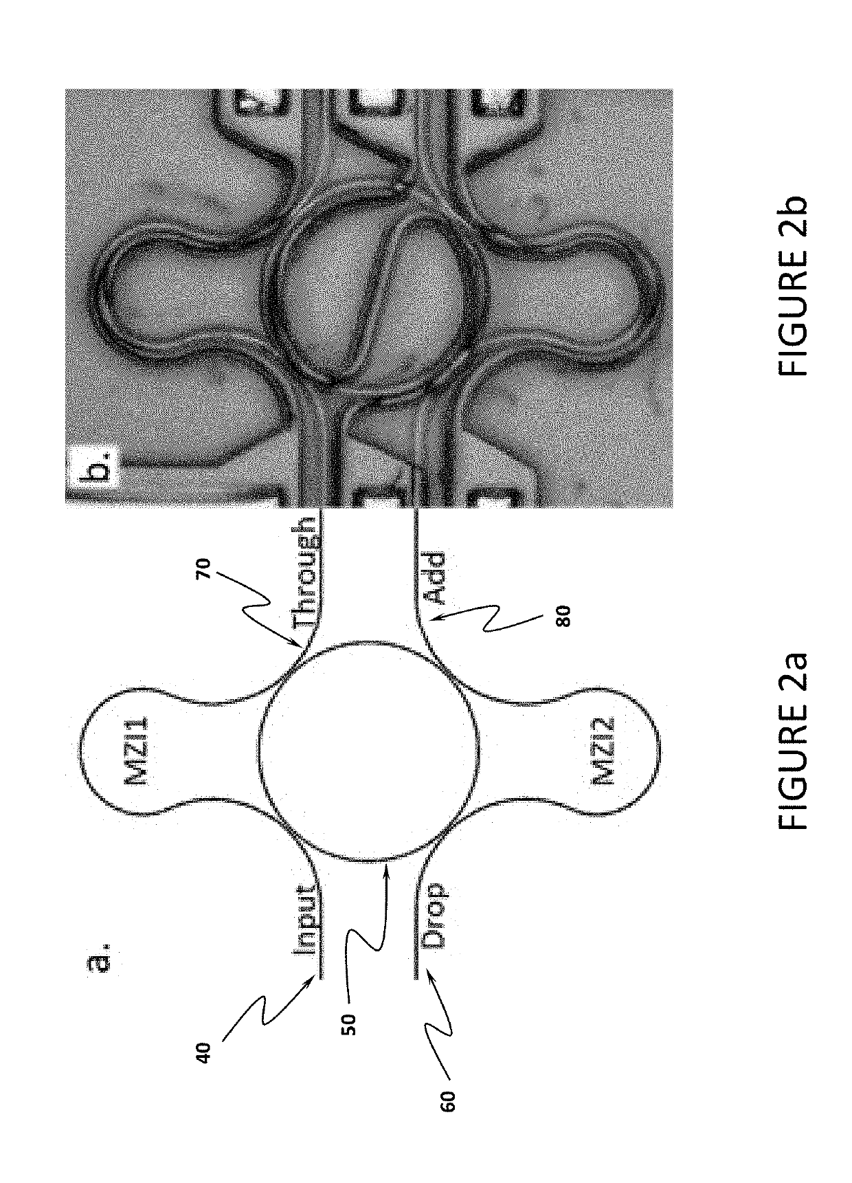
[0033]An object of the present invention is to devise a wavelength dependent means to split light. The present invention employs a Dual Mach-Zehnder (MZI) device having legs that are grossly misbalanced, wherein the MZI will have a wavelength dependence to its ability to split light. The present invention devises two unbalanced MZI, one which will perfectly transmit the pump wavelengths and partially reflect the signal wavelength. The other MZI will do the opposite, reflecting the pump wavelengths but perfectly transmitting the signal wavelength.

[0034]Referring to FIG. 2a and FIG. 2b, the present invention essentially makes a Mach-Zehnder interferometer (MZI) out of the input waveguide 40 and the ring 50. Being a cavity, the ring 50 will only support specific wavelengths of light (where the resonance condition is satisfied) separated by the free spectral range (FSR). The spectrum of an unbalanced MZI is sinusoidal with the difference in optical path length between the two paths dete...


PUM

PropertyMeasurementUnit
frequencyaaaaaaaaaa
relative phase delayaaaaaaaaaa
wavelengthsaaaaaaaaaa

Abstract

The invention provides an apparatus for optical integrated on-chip generation of photon pairs as a building block to create entangled photon states required for quantum information processing. The invention provided a frequency selective optical coupling device which controls the transmission of light by varying the relative dimensions of otherwise symmetrical linear optical waveguides tangential to an annular optical waveguide, thereby controlling the coupling of light between the linear optical waveguides and the annular optical waveguide. Dimensional change of the optical waveguides is achieved by a heated medium in proximity of the optical waveguides and under electronic control.

Description

RELATIONSHIP TO OTHER PENDING APPLICATIONS[0001]This patent application is a continuation of, cross references, and claims any and all priority benefit from U.S. patent application Ser. No. 15 / 813,442 filed on Nov. 15, 2017, now pending and incorporated by reference as if fully set forth herein.[0002]U.S. patent application Ser. No. 15 / 813,442 cross references and claims the priority benefit under 35 USC § 119(e) of the filing date of provisional application Ser. No. 62 / 424,739 having been filed in the United States Patent and Trademark Office on Nov. 21, 2016 and now incorporated by reference as if fully set forth herein.STATEMENT OF GOVERNMENT INTEREST[0003]The invention described herein may be manufactured and used by or for the Government for governmental purposes without the payment of any royalty thereon.TECHNICAL FIELD OF THE INVENTION[0004]This invention relates generally to the field of quantum information processing and more specifically to integrated photonic devices that...

Claims


Application Information

Patent Timeline
Patent Type & Authority Applications(United States)
IPC IPC(8): G02B6/26G02B6/12G02F1/225G02F1/313
CPCG02B6/26G02F1/225G02B6/12G02F1/3132G02F2203/055
Inventor FANTO, MICHAEL L.ALSING, PAUL M.TISON, CHRISTOPHER C.PREBLE, STEFAN F.STEIDLE, JEFFREY A.
Owner THE UNITED STATES OF AMERICA AS REPRESETNED BY THE SEC OF THE AIR FORCE
Features
  • R&D
  • Intellectual Property
  • Life Sciences
  • Materials
  • Tech Scout
  • Unparalleled Data Quality
  • Higher Quality Content
  • 60% Fewer Hallucinations
Learn More