Vehicle lighting system, vehicle system, and vehicle

a vehicle lighting and vehicle technology, applied in the direction of vehicle components, acoustic signal devices, pedestrian guidance indicators, etc., can solve the problems of inability to perform inter-vehicle communication, increased height of the vehicle, poor outer appearance of the vehicle,

Active Publication Date: 2019-06-06
KOITO MFG CO LTD
View PDF12 Cites 18 Cited by
  • Summary
  • Abstract
  • Description
  • Claims
  • Application Information

AI Technical Summary

Benefits of technology

The patent text talks about a system that can help prevent accidents between a car and a person or another car by recognizing them and showing them information about the car's intentions. The technical effect of this system is to make driving safer and prevent accidents.

Problems solved by technology

However, Patent Document 1 does not consider a vehicle illumination system and a vehicle system capable of presenting information, which indicates that the automatic driving vehicle recognizes a target object such as the pedestrian, the other vehicle and the like, to the target object.
Like this, when the display device is arranged on the vehicle body roof, a dimension of the vehicle in a height direction increases and an outer appearance of the vehicle is also poor.
Also, in Patent Document 1, when the display device mounted in each of the preceding vehicle and the following vehicle is out of order, inter-vehicle communication cannot be performed because there is no separate backup display device.
As a result, the other vehicle may intrude between the preceding vehicle and the following vehicle, so that the traveling safety of the following vehicle is degraded.
Meanwhile, in an automatic driving vehicle including an illumination system having a pedestrian-to-vehicle communication function, when the illumination system is out of order and a separate device configured to perform pedestrian-to-vehicle communication is not provided to the automatic driving vehicle, a possibility that the automatic driving vehicle may cause a traffic trouble with the pedestrian may increase.

Method used


Image

  • Vehicle lighting system, vehicle system, and vehicle
  • Vehicle lighting system, vehicle system, and vehicle
  • Vehicle lighting system, vehicle system, and vehicle

Examples


first embodiment

[0196]Hereinafter, a first embodiment will be described with reference to the drawings. Meanwhile, for the sake of convenience of descriptions, the description of members having the same reference numerals as those already described in the description of the first embodiment will be omitted. Also, for the sake of convenience of description, dimensions of the respective members shown in the drawings may be different from actual dimensions of the respective members.

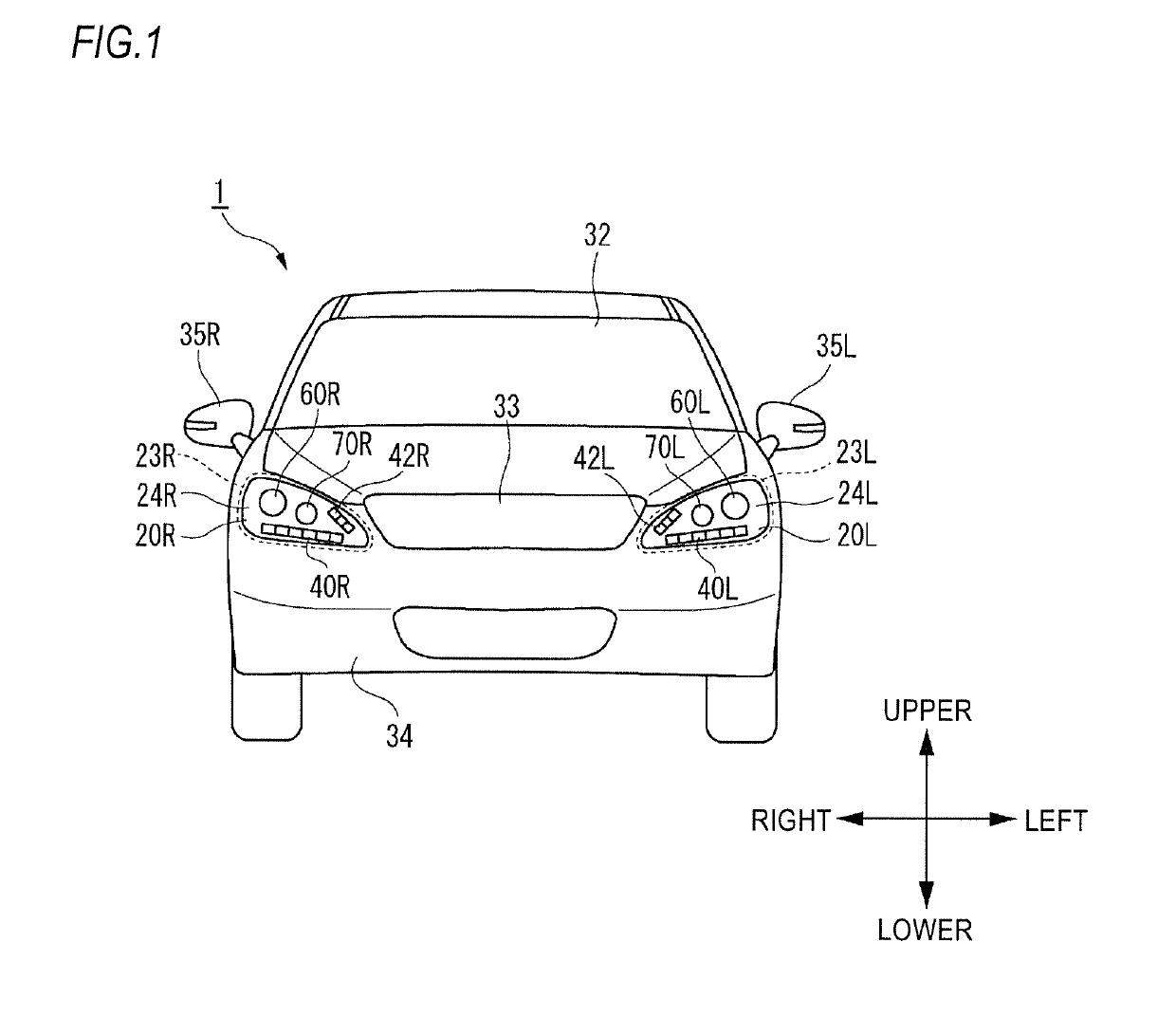
[0197]Also, in the description of the first embodiment, for the sake of convenience of description, “the right and left direction”, “the front and rear direction” and “the upper and lower direction” will be appropriately mentioned. The directions are relative directions set with respect to a vehicle 1 shown in FIG. 1. Here, “the upper and lower direction” is a direction including “the upward direction” and “the downward direction”. “The front and rear direction” is a direction including “the forward direction” and “the rear...

second embodiment

[0280]In the below, a vehicle 1B in accordance with a second embodiment is described with reference to FIGS. 15 and 2. FIG. 15 is a front view of the vehicle 1B having the illumination system 4 mounted thereto.

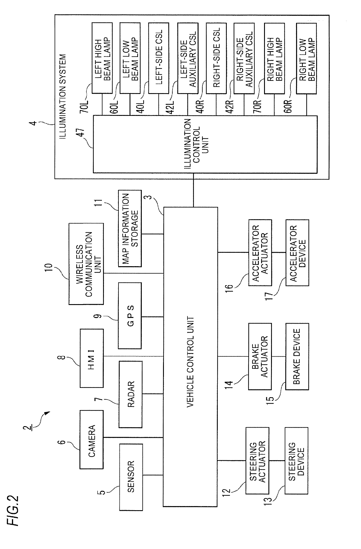
[0281]As shown in FIG. 15, the illumination system 4 (refer to FIG. 2) includes the left-side headlamp 20L, the left low beam lamp 60L, the right-side headlamp 20R, and the right low beam lamp 60R. The left-side headlamp 20L is mounted to a front left side of the vehicle 1B, and includes the housing 23L, the cover 24L mounted to the housing 23L, and the left high beam lamp 70L (second lamp). The cover 24L is configured by a light-penetrating member through which light can pass, for example. A lamp chamber is formed by the housing 23L and the cover 24L, and the left high beam lamp 70L is arranged in the lamp chamber. The left high beam lamp 70L is configured to emit the high beam toward the front of the vehicle 1B. The left low beam lamp 60L (first lamp) is arranged at the fron...

first modified embodiment

[0289]FIG. 16 is a front view of the vehicle 1B having an illumination system of the first modified embodiment. The illumination system shown in FIG. 16 is different from the illumination system shown in FIG. 15, in that the number of the low beam lamp is one. That is, in the illumination system shown in FIG. 15, the two low beam lamps (i.e., the left low beam lamp 60L and the right low beam lamp 60R) are arranged at the front grill 33. However, in the illumination system shown in FIG. 16, one low beam lamp 60 (first lamp) is arranged at the front grill 33.


PUM


Abstract

A vehicle illumination system for a vehicle capable of traveling in an automatic driving mode includes a left-side communication support lamp and a right-side communication support lamp configured to lit light toward an outside of the vehicle and arranged to be visually recognized from the front of the vehicle, and an illumination controller configured to, when the vehicle detects a target object, change an illumination state of at least one of the left-side communication support lamp and the right-side communication support lamp. Each of the left-side communication support lamp and the right-side communication support lamp includes a plurality of light-emitting segments arranged side by side in a right and left direction of the vehicle. The illumination controller is configured to change an illumination state of each of the plurality of light-emitting segments.

Description

CROSS-REFERENCE TO RELATED APPLICATIONS[0001]The present application is a national stage application of PCT / JP2017 / 025718, which claims priority to Japanese Patent Application No. 2016-149947 filed on Jul. 29, 2016, Japanese Patent Application No. 2016-149948 filed on Jul. 29, 2016, Japanese Patent Application No. 2016-149949 filed on Jul. 29, 2016, Japanese Patent Application No. 2016-149950 filed on Jul. 29, 2016, and Japanese Patent Application No. 2016-149951 filed on Jul. 29, 2016, the contents of which are incorporated herein in their entirety.BACKGROUNDTechnical Field[0002]The present disclosure relates to a vehicle illumination system. In particular, the present disclosure relates to a vehicle illumination system provided to a vehicle capable of traveling in an automatic driving mode. Also, the present disclosure relates to a vehicle system having the vehicle illumination system, and a vehicle having the vehicle system.Related Art[0003]Currently, research on an automatic dri...

Claims


Application Information

Patent Timeline
Patent Type & Authority Applications(United States)
IPC IPC(8): B60Q1/50B60Q1/04B60Q1/44B60Q9/00
CPCB60Q1/50B60Q1/0408B60Q1/445B60Q9/008B60Q2300/45B60Q2400/30B60Q2400/20B60Q1/2607B60Q1/38B60Q5/006G08G1/005B60Q9/00B60Q5/005B60Q2900/40B60Q1/503B60Q1/543B60Q1/507
Inventor TATARA, NAOKIOKAMURA, TOSHIHIROMASUDA, TAKESHI
Owner KOITO MFG CO LTD
Why Eureka
Try Eureka