
Radar apparatus

Active Publication Date: 2020-01-23
DENSO TEN LTD
View PDF0 Cites 2 Cited by
  • Summary
  • Abstract
  • Description
  • Claims
  • Application Information

AI Technical Summary

Benefits of technology

The radar apparatus can prevent a wrong tracking of a target that is difficult to be detected. The technical effect is to improve the accuracy of radar tracking.

Problems solved by technology

However, the radar apparatus performs a wrong tracking such that the attention target that has actually moved out of the FOV remains within the FOV.
However, such a radar apparatus has not prevented the wrong tracking shown in FIG. 14.

Method used


Image

  • Radar apparatus
  • Radar apparatus
  • Radar apparatus

Examples


Embodiment Construction

[0025]Exemplified embodiments of the invention will be hereinafter described in detail with reference to the drawings.

1. Configuration of Radar Apparatus

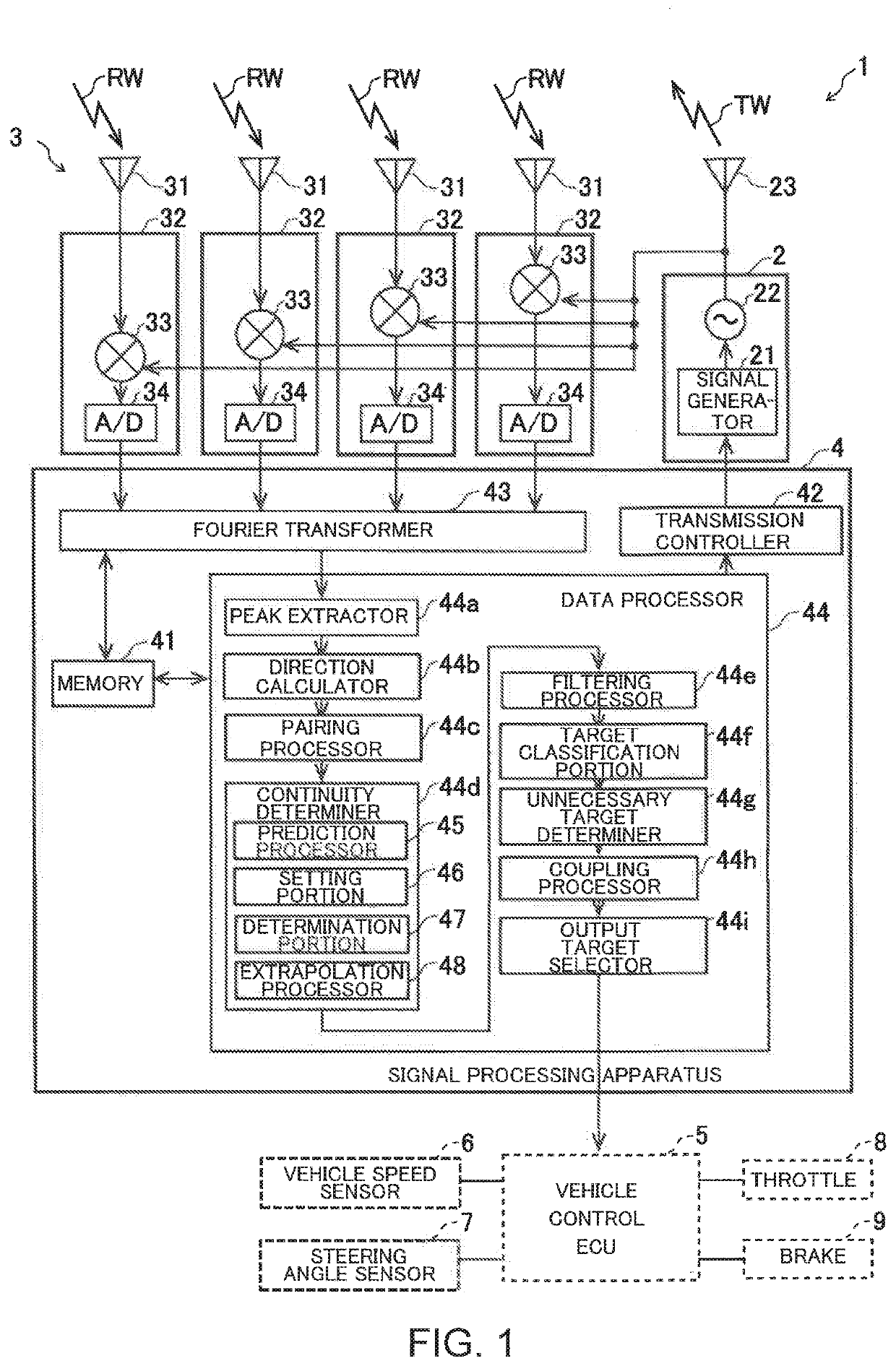
[0026]FIG. 1 illustrates a configuration of a radar apparatus 1 according to this embodiment. The radar apparatus 1 is, for example, mounted on a vehicle, such as a car. The vehicle on which the radar apparatus 1 is mounted is hereinafter referred to as “host vehicle”. Moreover, a straight traveling direction of the host vehicle, which is a direction from a driver's seat toward a steering, is referred to as “front direction”. A straight traveling direction of the host vehicle, which is a direction from the steering toward the driver's seat, is referred to as “back direction”. A direction perpendicular to the straight traveling direction of the host vehicle and a vertical line, which is a direction from a right side toward a left side of a driver who faces forward, is referred to as “left direction”. A direction perpendicular to the ...


PUM


Abstract

A radar apparatus detects objects in a vicinity of a host vehicle on which the radar apparatus is mounted. The radar apparatus includes a microcomputer configured to operate as a prediction processor that calculates a prediction position of a previously detected target in a current detection cycle and an extrapolation processor that executes an extrapolation to determine that a same target as the previously detected target exists in the prediction position for the current detection cycle. The extrapolation processor executes the extrapolation when the prediction position is outside a detection range of the radar apparatus and a speed of the host vehicle is lower than a predetermined value.

Description

BACKGROUND OF THE INVENTIONField of the Invention[0001]The invention relates to a technology for tracking a target that is detected by a radar apparatus.Description of the Background Art[0002]In a front-side radar apparatus, there are many situations in which an object crosses a detection range (FOV: field of view) of the radar apparatus. This is because a direction of the radar apparatus is different from a moving direction of a host vehicle, and there is a situation in which the host vehicle bumps into another vehicle as a situation to be detected, and the like. Such an object moves out of the FOV of the radar apparatus from within the FOV of the radar apparatus.[0003]For example, when the front-side radar apparatus detects a guardrail pole, regularly aligned diamond-shaped targets shown in FIG. 14 are detected. In FIG. 14, a range of angle θ is within the FOV. Here, an attention target is shown by a black diamond shape. In situations shown in PATTERN A, PATTERN B and PATTERN C in...

Claims


Application Information

Patent Timeline
IPC IPC(8): G01S13/72G01S13/93G01S13/931
CPCG01S2013/932G01S13/931G01S13/723G01S2013/9321G01S13/726G01S13/584G01S7/354G01S13/87G01S2013/93271
Inventor AOKI, SHINYAFUJITSU, SEIYA
Owner DENSO TEN LTD
Learn More