
Shaped stator windings for a switched reluctance machine and method of making the same

a switched reluctance machine and stator winding technology, which is applied in the direction of synchronous motors, magnetic circuit shapes/forms/construction, dynamo-electric components, etc., can solve the problems of inability to fully utilize the potential copper fill factor, the assembly of the machine is complicated, and the approach fails to produce curved stator windings that conform to the stator curved shape, etc., to achieve more torque, increase speed, and increase power density

Pending Publication Date: 2020-06-04
TURNTIDE TECH INC
View PDF2 Cites 7 Cited by
  • Summary
  • Abstract
  • Description
  • Claims
  • Application Information

AI Technical Summary

Benefits of technology

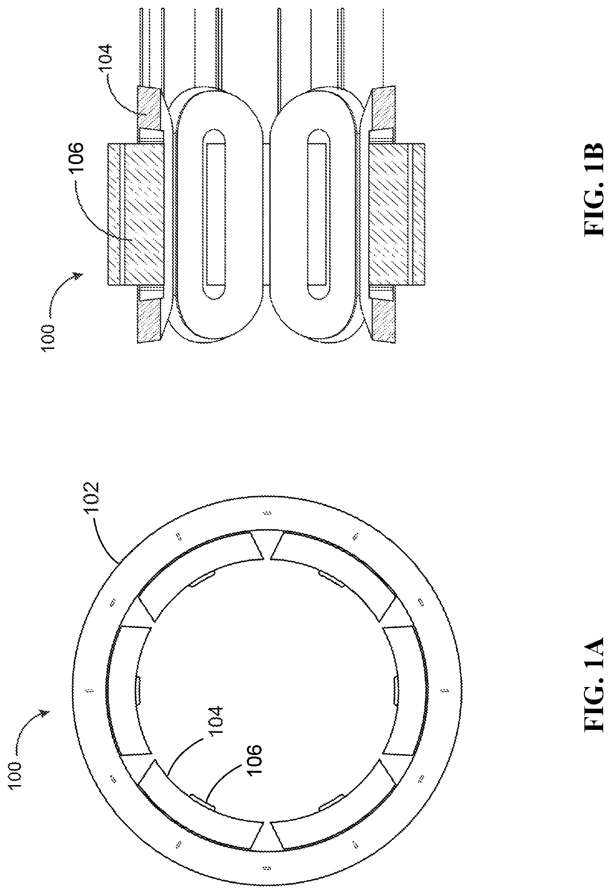
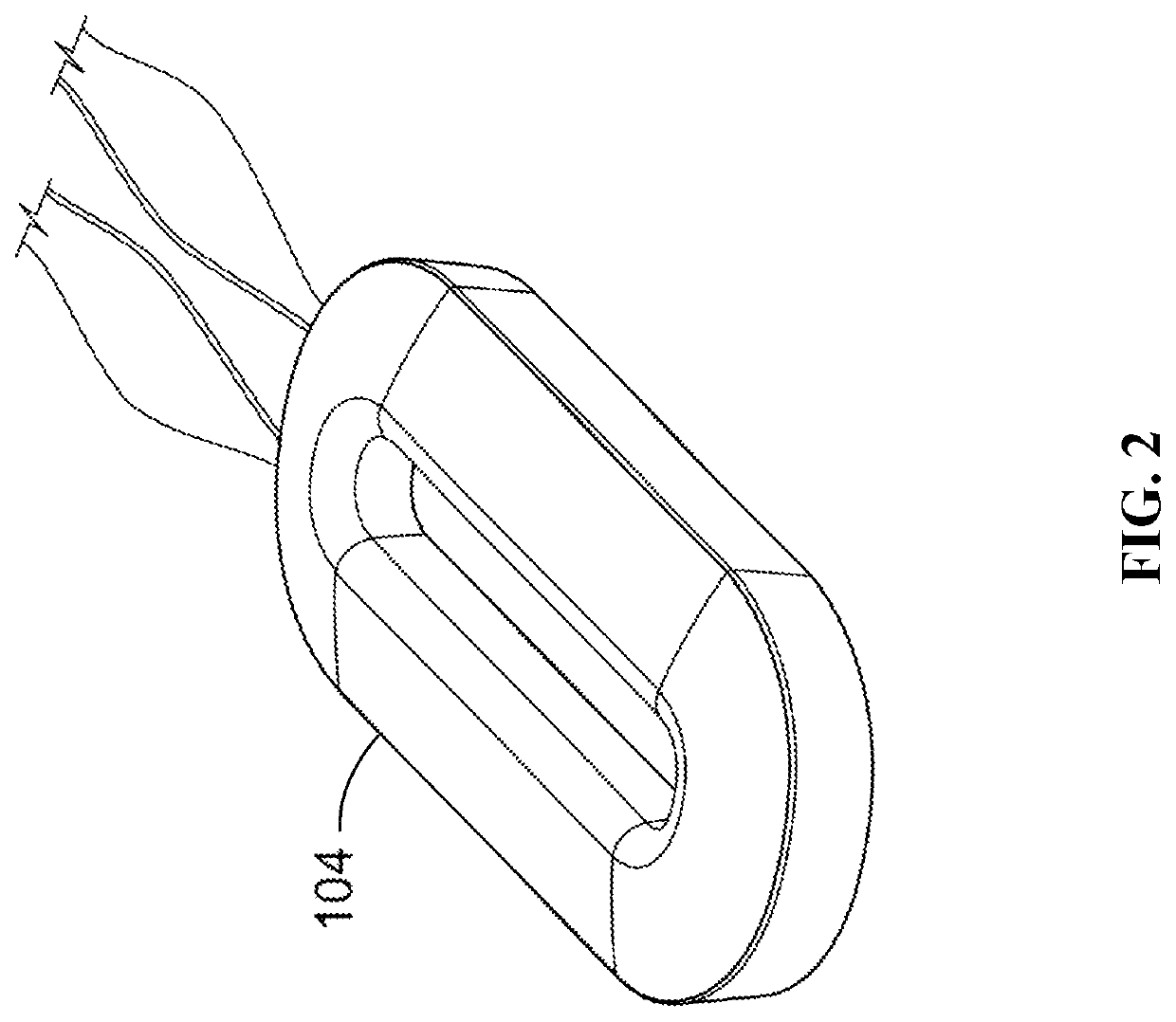
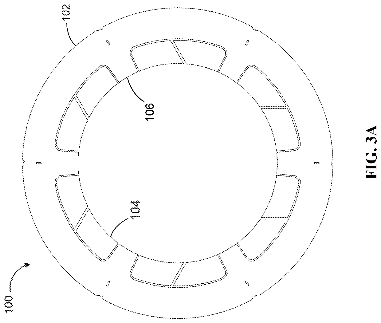
The present invention provides a process for shaping multiple stator windings for a switched reluctance machine. These windings are designed to highly conform to the stator shape, allowing for improved performance including higher efficiency, lower noise, and higher torque. The use of curved stator windings increases the copper fill factor, resulting in increased efficiency and reduced noise. The invention also aims to produce curved stator windings that enable higher efficiency and lower noise in a switched reluctance machine.

Problems solved by technology

However, this conventional approach fails to produce curved stator windings conforming to the stator curved shape.
Also, this approach fails to fully utilize the potential copper fill factor.
This assembly of the machine is complicated.
Further, this conventional approach does not teach shaping of the windings and does not facilitate formation of stator shape-conforming windings for SRMs.
However, this approach does not follow a two-step process to achieve the shaping of the windings.
Furthermore, this approach fails to produce curved stator windings conforming to the stator curved shape.

Method used


Image

  • Shaped stator windings for a switched reluctance machine and method of making the same
  • Shaped stator windings for a switched reluctance machine and method of making the same
  • Shaped stator windings for a switched reluctance machine and method of making the same

Examples


Embodiment Construction

[0027]In the following discussion that addresses a number of embodiments and applications of the present invention, reference is made to the accompanying drawings that form a part hereof, and in which is shown by way of illustrating specific embodiments in which the invention may be practiced. It is to be understood that other embodiments may be utilized, and changes may be made without departing from the scope of the present invention.

[0028]Various inventive features are described below that can each be used independently of one another or in combination with other features. However, any single inventive feature may not address any of the problems discussed above or only address one of the problems discussed above. Further, one or more of the problems discussed above may not be fully addressed by any of the features described below. In the following discussion that addresses a number of embodiments and applications of the present invention, reference is made to the accompanying dra...


PUM


Abstract

The present invention is a method for producing a plurality of curved stator windings by shaping a plurality of stator coils for a switched reluctance machine (SRM). The present invention proposes apparatus and methods for utilizing a plurality of curved stator windings with two main embodiments: a symmetrical winding and an asymmetrical winding, whereby the plurality of curved stator windings are highly conforming to a curved stator shape. The plurality of curved stator windings provides higher efficiency and lower noise to the SRM. The plurality of curved stator windings conforms to the stator curved shape, maximizing the copper fill factor, thereby permitting maximum copper utilization in the machine.

Description

PRIORITY[0001]This application claims priority from the United States provisional application with Ser. No. 62 / 744,707 and filed Oct. 12, 2018. The disclosure of that provisional application is incorporated herein as if set out in full.DESCRIPTION OF THE RELATED ARTTechnical Field of the Disclosure[0002]This invention relates in general to stator windings for switched reluctance machines. More particularly, this invention relates to shaped windings that are highly conforming to the stator shape and stator pole shape of a switched reluctance machine.Background of the Disclosure[0003]A switched reluctance machine (SRM) is a doubly salient machine, that is, it comprises multiple poles on both stator and rotor. The SRM may have a plurality of stator poles, each with multiple loops of electrically conductive wires or in total a coil or winding positioned thereabout. The stator poles of the SRM are integral parts of the stator. The stator windings comprising each machine phase winding are...

Claims


Application Information

Patent Timeline
Patent Type & Authority Applications(United States)
IPC IPC(8): H02K3/18H02K1/14H02K15/04H02K15/06
CPCH02K1/145H02K15/065H02K15/045H02K3/18H02K19/02
Inventor DESAI, PIYUSHHU, EDGARJOHNSTON, MARK
Owner TURNTIDE TECH INC
Learn More