Imaging lens
a technology of imaging lens and aperture, applied in the field of imaging lens, can solve the problems of insufficient size reduction and difficult cost reduction, and achieve the effect of facilitating aberration correction, facilitating aberration correction, and facilitating aberration correction
- Summary
- Abstract
- Description
- Claims
- Application Information
AI Technical Summary
Benefits of technology
Problems solved by technology
Method used
Image

Examples
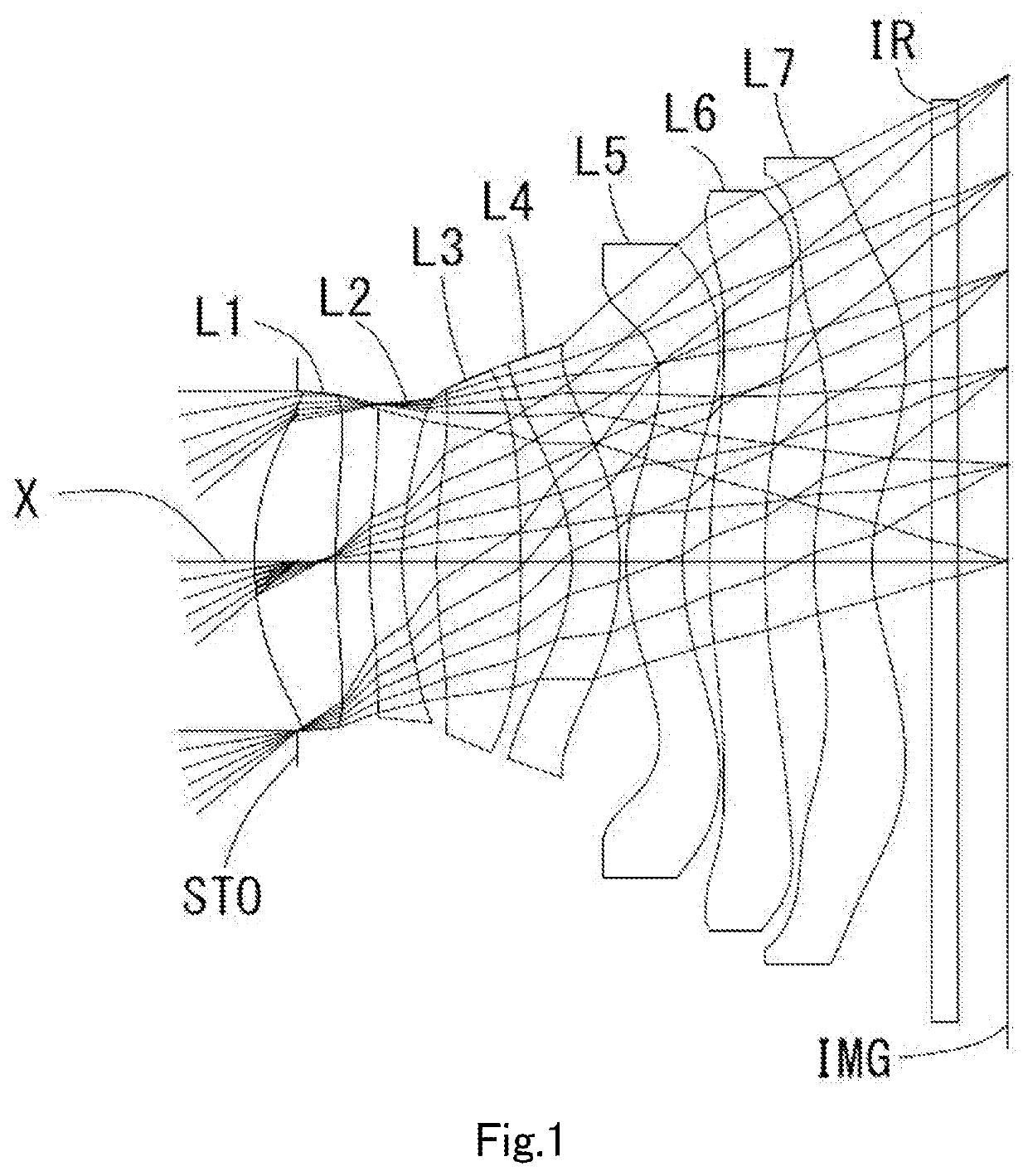
example 1
[0085]The basic lens data is shown below in Table 1.
TABLE 1Unit mmf =4.79ih =4.03Fno =1.70TTL =6.20ω(°) =39.5Surface DataSurfaceCurvatureSurfaceRefractiveAbbeNumber iRadius rDistance dIndex NdNumber vdFocal Length(Object)InfinityInfinity1 (Stop)Infinity−0.3625 2*2.3112(r1)0.6767(d1)1.5445(Nd1)55.98(vd1)6.62(=f1) 3*5.7779(r2)02821(t1) 4*3.4809(r3)0.2720(d2)1.6612(Nd2)20.37(vd2)−14.46(=f2) 5*2.4726(r4)0.2866(t2) 6*5.1708(r5)0.7032(d3)1.5445(Nd3)55.98(vd3)6.15(=f3) 7*−9.0345(r6)0.4197(t3) 8*−1.4464(r7)0.4000(d4)1.6397(Nd4)23.53(vd4)−8.00(=f4) 9*−2.2335(r8)0.0550(t4)10*1.9035(r9)0.4700(d5)1.5445(Nd5)55.98(vd5)9.01(=f5)11*2.8398(r10)0.2231(t5)12*7.0077(r11)0.4600(d6)1.5445(Nd6)55.98(vd6)126.06(=f6)13*7.6239(r12)0.4079(t6)14*2.4638(r13)0.4850(d7)1.5348(Nd7)55.66(vd7)−11.02(=f7)15*1.6183(r14)0.278816 Infinity0.21001.563051.3017 Infinity0.6462(ImageInfinityPlane)Lens group dataComposite Focal LengthEnhance Pupil Diameter1st lens-2nd lens10.14(=f12)2.810(=EPD)2nd lens-3rd lens10.68(=f23)3rd ...
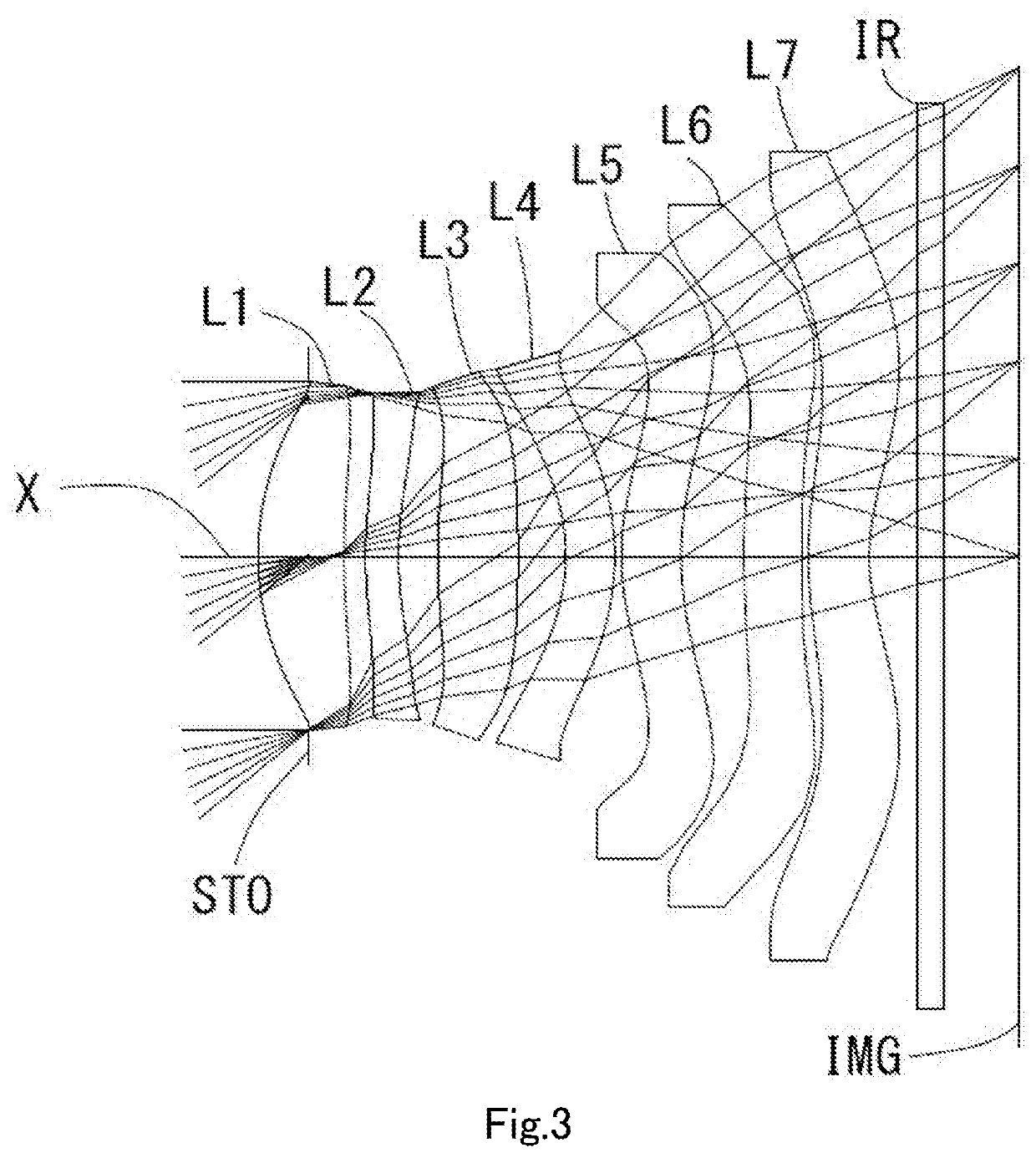
example 2
[0088]The basic lens data is shown below in Table 2.
TABLE 2Unit mmf =4.88ih =4.03Fno =1.70TTL =6.20ω(°) =39.1Surface DataSurfaceCurvatureSurfaceRefractiveAbbeNumber iRadius rDistance dIndex NdNumber vdFocal Length(Object)InfinityInfinity1 (Stop)Infinity−0.4150 2*2.3033(r1)0.7070(d1)1.5445(Nd1)55.98(vd1)8.86(=f1) 3*5.3516(r2)0.1782(t1) 4*3.3985(r3)0.2721(d2)1.6709(Nd2)19.48(vd2)−24.87(=f2) 5*2.7326(r4)0.3239(t2) 6*5.8363(r5)0.6605(d3)1.5445(Nd3)55.98(vd3)7.16(=f3) 7*−11.2520(r6)0.3962(t3) 8*−1.5256(r7)0.4000(d4)1.6512(Nd4)20.37(vd4)−8.93(=f4) 9*−2.2715(r8)0.0550(t4)10*1.9695(r9)0.4933(d5)1.5445(Nd5)55.98(vd5)11.75(=f5)11*2.5938(r10)0.5193(t5)12*10.3411(r11)0.4800(d6)1.5348(Nd6)55.66(vd6)11.82(=f6)13*−16.0000(r12)0.0500(t6)14*3.4484(r13)0.5009(d7)1.5348(Nd7)55.66(vd7)−6.14(=f7)15*1.5973(r14)0.248816 Infinity0.21001.563051.3017 Infinity0.7766(ImageInfinityPlane)Lens group dataComposite Focal LengthEnhance Pupil Diameter1st lens-2nd lens8.57(=f12)2.865(=EPD)2nd lens-3rd lens10.24(=f23)3...
example 3
[0091]The basic lens data is shown below in Table 3.
TABLE 3Unit mmf =4.90ih =4.03Fno =1.70TTL =6.20ω(°) =38.9Surface DataSurfaceCurvatureSurfaceRefractiveAbbeNumber iRadius rDistance dIndex NdNumber vdFocal Length(Object)InfinityInfinity1 (Stop)Infinity−0.4350 2*2.2617(r1)0.7274(d1)1.5445(Nd1)55.98(vd1)6.62(=f1) 3*5.3795(r2)0.1796(t1) 4*3.6532(r3)0.2720(d2)1.6709(Nd2)19.48(vd2)−22.85(=f2) 5*2.8619(r4)0.3243(t2) 6*5.6975(r5)0.6303(d3)1.5445(Nd3)55.98(vd3)7.35(=f3) 7*−12.9039(r6)0.3866(t3) 8*−1.4840(r7)0.4000(d4)1.6612(Nd4)20.37(vd4)−8.62(=f4) 9*−2.2216(r8)0.0559(t4)10*1.9158(r9)0.4706(d5)1.5445(Nd5)55.98(vd5)11.19(=f5)11*2.5525(r10)0.5688(t5)12*9.1813(r11)0.4800(d6)1.5348(Nd6)55.66(vd6)11.32(=f6)13*−17.4581(r12)0.0599(t6)14*3.8367(r13)0.4926(d7)1.5348(Nd7)55.66(vd7)−6.06(=f7)15*1.6781(r14)0.237116 lnflntiv0.21001.563051.3017 InMy0.7757(ImageInfinityPlane)Lens group dataComposite Focal LengthEnhance Pupil Diameter1st lens-2nd lens8.39(=f12)2.880(=EPD)2nd lens-3rd lens10.99(=f23)3rd le...
PUM
 Abstract
Description
Claims
Application Information
 - R&D
- Intellectual Property
- Life Sciences
- Materials
- Tech Scout
- Unparalleled Data Quality
- Higher Quality Content
- 60% Fewer Hallucinations
Browse by: Latest US Patents, China's latest patents, Technical Efficacy Thesaurus, Application Domain, Technology Topic, Popular Technical Reports.
© 2025 PatSnap. All rights reserved.Legal|Privacy policy|Modern Slavery Act Transparency Statement|Sitemap|About US| Contact US: help@patsnap.com