Check patentability & draft patents in minutes with Patsnap Eureka AI!

Shield terminal and shield connector

a shield terminal and shield connector technology, applied in the direction of coupling contact members, coupling device connections, connections effected by permanent deformation, etc., can solve the problem that the resiliently deflectable locking lance may be disengaged from the locking projection

Active Publication Date: 2021-05-13
AUTONETWORKS TECH LTD +2
View PDF0 Cites 0 Cited by
  • Summary
  • Abstract
  • Description
  • Claims
  • Application Information

AI Technical Summary

Benefits of technology

The patent text describes a design for a connector that has two locking parts on its outer surface. These parts are positioned on the same plane and at different positions in the width direction. This arrangement prevents interference between the locking parts and ensures that the first locking part does not interfere with a side retainer and the second locking part does not interfere with the first and second locking lances. The technical effect of this configuration is a more reliable and secure connection between two components.

Problems solved by technology

There is a concern that the resiliently deflectable locking lance may be disengaged from the locking projection due to an impact, vibration or the like.

Method used


Image

  • Shield terminal and shield connector
  • Shield terminal and shield connector
  • Shield terminal and shield connector

Examples


Embodiment Construction

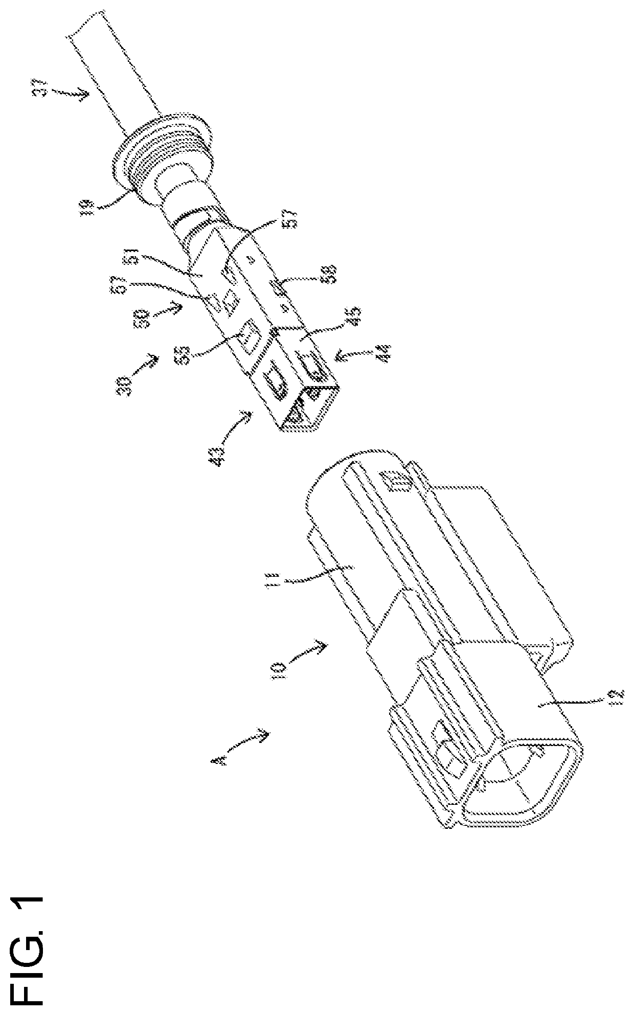
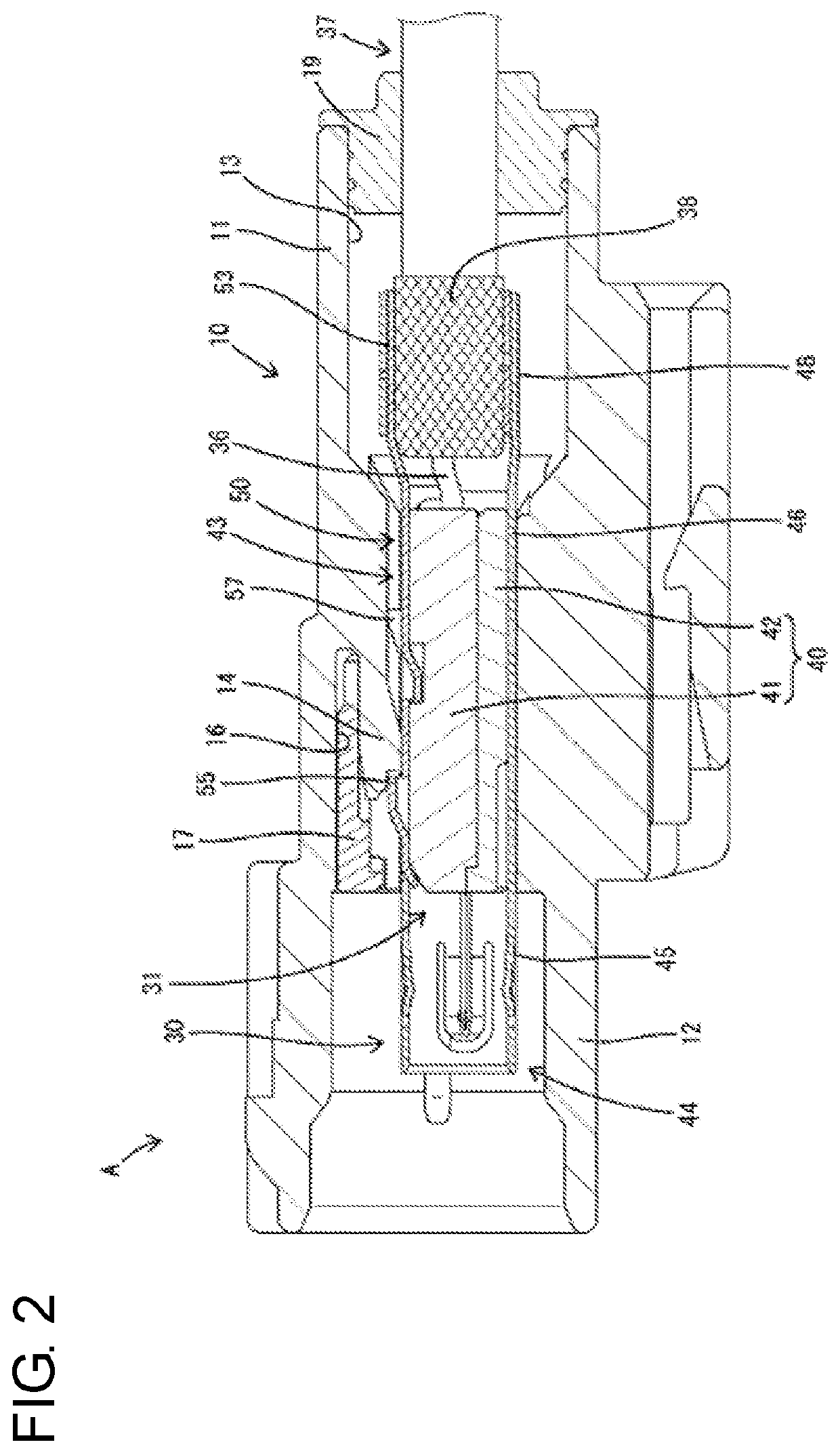
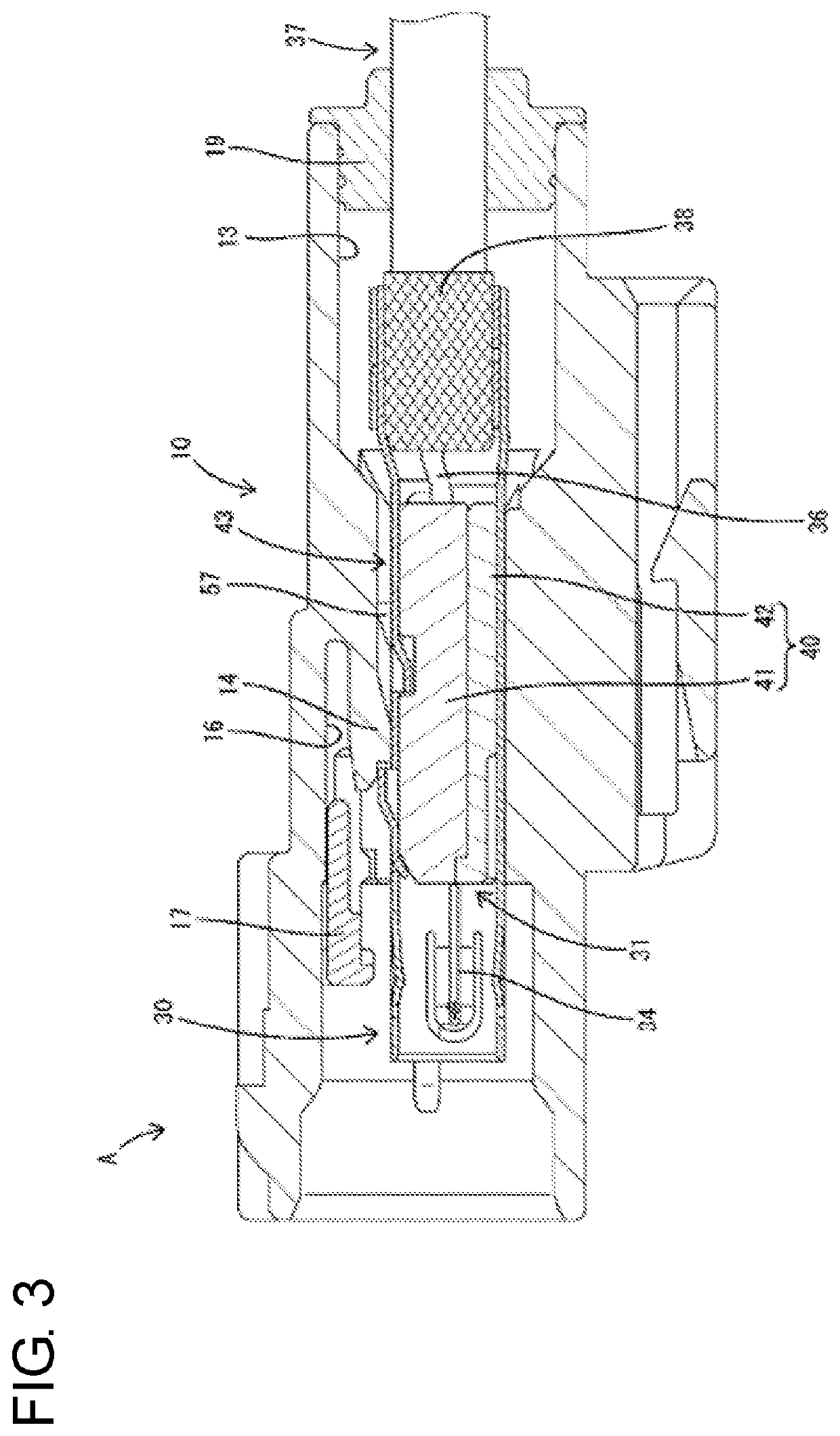
[0022]An embodiment of the invention is described with reference to FIGS. 1 to 11. Note that, in the following description, a left side in FIGS. 1 to 11 is defined as a front side concerning a front-rear direction. Upper and lower sides shown in FIGS. 1 to 3, 5 to 8, 10 and 11 are directly defined as upper and lower sides concerning a vertical direction. A shield terminal 30 of this embodiment constitutes a first shield connector A (shield connector as claimed) of a waterproof type by being mounted into a first housing 10 and constitutes a second shield connector B (shield connector as claimed) of a non-waterproof type by being mounted into a second housing 20.

[0023]The first housing 10 is made of synthetic resin and, as shown in FIGS. 2 to 4, is a single component including an accommodating portion 11 and a receptacle 12 extending forward from the outer periphery of the front end of the accommodating portion 11. A first accommodation chamber 13 is formed inside the accommodating po...


PUM


Abstract

A shield terminal (30) includes a dielectric (40) configured to accommodate inner conductors (32) and an outer conductor (43) surrounding the dielectric (40), and is mountable into a selected one of first housing (10) and a second housing (20). A first locking portion (55) and second locking portions (57) are formed on an outer surface of the outer conductor (40). The shield terminal (30) inserted into a first accommodation chamber (13) is retained by a front retainer (17) restricting the resilient deflection of a first locking lance (14) and the first locking portion (55) being to the first locking lance (14). The shield terminal (30) inserted into a second accommodation chamber (21) is retained by the locking of the first locking portion (55) and a second locking lance (22) and the locking of the second locking portions (57) and a side retainer (24).

Description

BACKGROUNDField of the Invention[0001]The invention relates to a shield terminal and a shield connector.Related Art[0002]Japanese Unexamined Patent Publication No. 2012-129103 discloses a shield connector with a terminal unit that has an inner conductor terminal in a dielectric. An outer conductor forms a shield terminal by surrounding the terminal unit and a housing accommodates the shield terminal. A resiliently deflectable locking lance is formed in the housing and is locked to a locking projection formed on an outer surface of the outer conductor for retaining and holding the shield terminal in the housing.[0003]There is a concern that the resiliently deflectable locking lance may be disengaged from the locking projection due to an impact, vibration or the like. Thus, it is desired to improve the reliability of a function for retaining the shield terminal.[0004]The invention was completed on the basis of the above situation and aims to improve the reliability of a function for r...

Claims


Application Information

Patent Timeline
Patent Type & Authority Applications(United States)
IPC IPC(8): H01R13/6581H01R13/422
CPCH01R13/6581H01R13/4226H01R13/04H01R13/4223H01R13/6593H01R4/18H01R4/184H01R9/0518H01R13/506H01R13/648H01R13/6582H01R13/6592H01R13/65912
Inventor MAESOBA, HIROYOSHIICHIO, TOSHIFUMI
Owner AUTONETWORKS TECH LTD
Features
  • R&D
  • Intellectual Property
  • Life Sciences
  • Materials
  • Tech Scout
  • Unparalleled Data Quality
  • Higher Quality Content
  • 60% Fewer Hallucinations
Learn More