Supercharge Your Innovation With Domain-Expert AI Agents!

Wastegate valve

a wastegate valve and turbine technology, applied in the direction of engines, mechanical equipment, machines/engines, etc., can solve the problems of increasing emissions, reducing the efficiency of catalytic converters, and reducing the efficiency of catalysts, so as to reduce the momentum change and hence the enthalpy loss

Active Publication Date: 2021-06-24
JAGUAR LAND ROVER LTD
View PDF2 Cites 0 Cited by
  • Summary
  • Abstract
  • Description
  • Claims
  • Application Information

AI Technical Summary

Benefits of technology

This solution effectively reduces the time for the catalytic converter to reach operating temperature, minimizing emissions during startup by efficiently directing hot gases onto the converter, even in smaller engines and larger vehicles.

Problems solved by technology

The combustion of petrol and diesel produces environmentally deleterious emissions.
Accordingly, at non-stoichiometric combustion mixes and low catalyst temperature there is a risk that emissions can be increased.
Until the temperature is raised sufficiently the catalytic converter will not be optimally effective and hence emissions will likely be higher than desired.
Thus, turbochargers typically have a high thermal inertia and, because the turbocharger is usually positioned upstream of the catalytic converter, cause a reduction in exhaust gas temperature reaching the catalytic converter in, or just after, start-up conditions.
Accordingly, until such time as the entire exhaust system reaches at least a degree of thermal equilibrium it is possible that the catalytic converter will not be heated to its optimum operating temperature and / or to the light off temperature and hence will not be as effective in reducing emissions.
However, a reduction in engine size will likely reduce the heat available to the catalyst, while the thermal mass of the intervening components (including the turbocharger, if present) is likely to remain the same or increase, further exacerbating the problem.
A downward pressure on engine size for vehicles (e.g. SUVs) will exacerbate the heating problem for the larger vehicles.
Clearly, such a solution is likely to add cost and complexity to an exhaust gas system.
For example, deploying such a solution is likely to be problematic in terms of mass production.
Moreover, in certain diesel vehicles where a diesel oxidation catalyst (DOC) is combined with a diesel particulate filter (DPF) local heating of the DPF without an associated air flow can lead to a combustion risk.

Method used


Image

  • Wastegate valve
  • Wastegate valve
  • Wastegate valve

Examples


Embodiment Construction

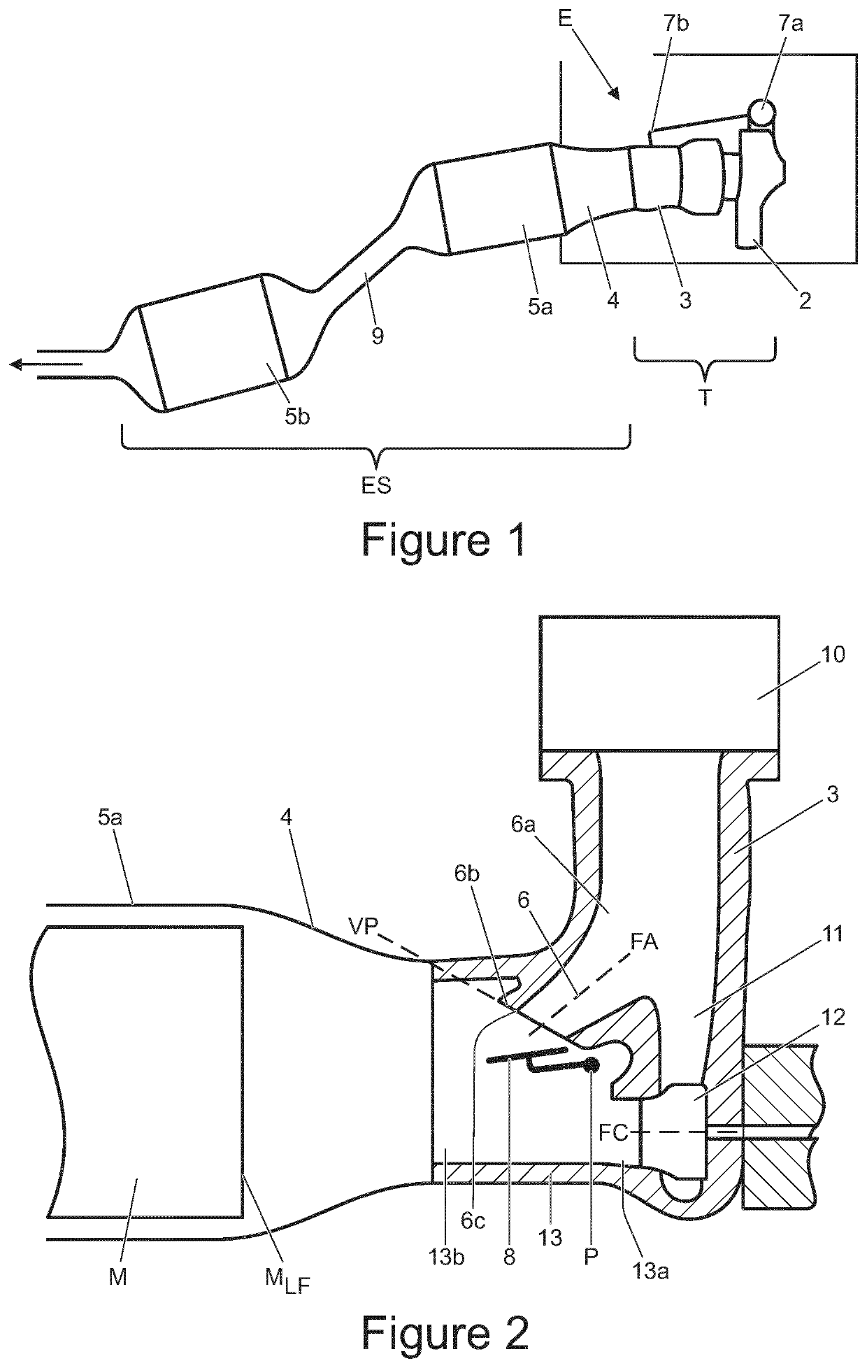
[0045]Referring first to FIG. 1, there is shown an engine E for a motor vehicle. The engine E is provided with a turbocharger unit T which is operably connected and secured to an exhaust system ES. The turbocharger unit T comprises a turbocharger compressor housing 2 and a turbocharger turbine housing 3. In flow sequence and operably connected to the turbocharger unit T, the exhaust system ES comprises a catalyst inlet cone 4, a primary catalytic converter 5a, a secondary catalytic converter 5b coupled to the rest of the exhaust system ES which typically directs exhaust emissions toward the rear of the vehicle. A catalyst downpipe 9 interconnects the primary and secondary catalytic converters 5a, 5b.

[0046]The turbocharger unit T may comprise a twin scroll turbocharger but any turbocharger unit may be used. It will be understood that the present invention may be especially applicable to vehicles that are provided with twin scroll turbochargers, because such turbochargers typically h...


PUM


Abstract

A wastegate valve for a bypass path for a turbocharger in an internal combustion engine, the wastegate valve comprises a valve seat defining a plane which is non-orthogonal to the principal flow axis for gases flowing along the bypass path and a valve member pivotable from an open position to a closed position, wherein in the closed position the valve member is seated on the valve seat, and in a fully open position the valve member is positioned to direct gases exiting the bypass path onto a leading face of a catalytic converter monolith for heating the monolith.

Description

TECHNICAL FIELD[0001]This invention relates to a turbocharger turbine wastegate valve, commonly referred to as a wastegate valve. Aspects of the invention relate to an exhaust system for an internal combustion engine and a method of heating a catalytic converter associated with an internal combustion engine.BACKGROUND[0002]It is well known that there is a need and desire to decrease certain emissions from motor vehicles powered by internal combustion (IC) engines. The combustion of petrol and diesel produces environmentally deleterious emissions. Typically such emissions comprise hydrocarbons (HCs), carbon monoxide (CO), nitrous oxides (NOx) and particulate matter.[0003]Over the years various modifications to IC engines have been made to improve efficiency and to reduce deleterious emissions. An important historical development to reduce such emissions involved the installation of catalytic convertors in the exhaust system of IC engine equipped motor vehicles.[0004]In petrol-powered...

Claims


Application Information

Patent Timeline
Patent Type & Authority Applications(United States)
IPC IPC(8): F02B37/18F01N3/20F02B37/22F01N3/28
CPCF02B37/183F01N3/2006F02B37/22Y02T10/12F02B37/18F01N2340/06F01N3/2892F01N3/101F01N13/00F01N2240/36F01N3/18F01N3/20F02B51/02F01N2430/00
Inventor ALBRECHT, MATTHEWSCHLARB, GUIDO
Owner JAGUAR LAND ROVER LTD
Features
  • R&D
  • Intellectual Property
  • Life Sciences
  • Materials
  • Tech Scout
  • Unparalleled Data Quality
  • Higher Quality Content
  • 60% Fewer Hallucinations
Learn More