Supercharge Your Innovation With Domain-Expert AI Agents!

Solar panel racking system

a solar array and solar panel technology, applied in the direction of solar thermal energy generation, climate sustainability, sustainable buildings, etc., can solve the problems of adding the risk of component damage and improper installation, human error, carelessness, etc., to reduce the installation cost of solar arrays, reduce aerodynamic forces, and improve positional stability

Active Publication Date: 2021-08-05
THE UNITED STATES AS REPRESENTED BY THE DEPARTMENT OF ENERGY
View PDF0 Cites 0 Cited by
  • Summary
  • Abstract
  • Description
  • Claims
  • Application Information

AI Technical Summary

Benefits of technology

The present patent provides a rack system for solar panels that is cost-effective and efficient. The rack channel is made on-site from sheet metal, eliminating the need for inventory and multiple handling steps. The rack channel is designed to withstand heavy loads and is anchored to a bearing surface using ballast blocks. The continuous design of the rack channel reduces aerodynamic forces, allowing for less ballast to be used. The proposed system can reduce installation and overall costs by about 9%.

Problems solved by technology

Besides assembly, costs associated with these multiple component systems can include their separate purchase, handling, inventorying, shipping, and allowances for loss, particularly of small parts.
Required on-site manual assembly of prior systems adds the risk of component damage and improper installation through human error, carelessness, inattention, or the like.
Unintended delays in shipping from a manufacturer to a site, and the risk of damage of system components when in transit or even the complete loss of a system or of separate parts of divided shipments add to overall costs.
Another significant disadvantage of conventional solar panel support systems were size limitations imposed by delivery methods of the multiple parts described above.

Method used


Image

  • Solar panel racking system
  • Solar panel racking system
  • Solar panel racking system

Examples


Embodiment Construction

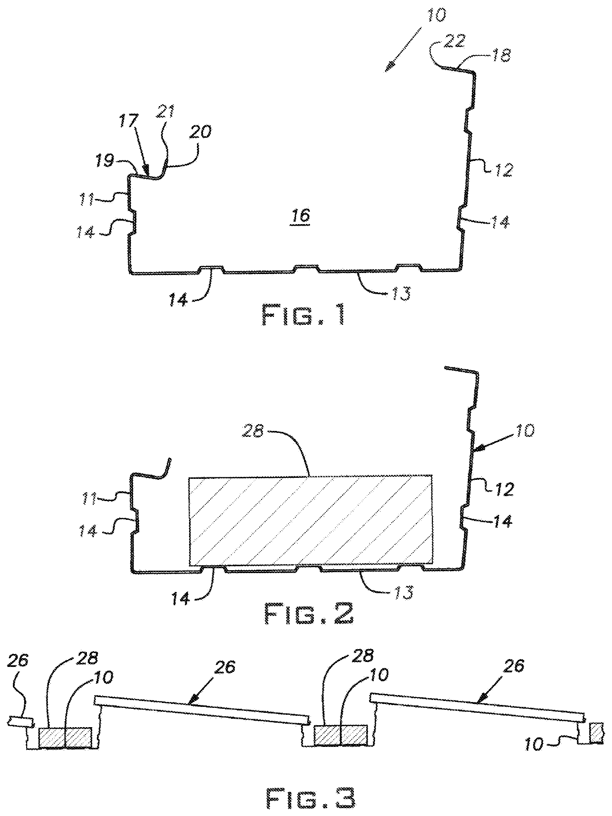
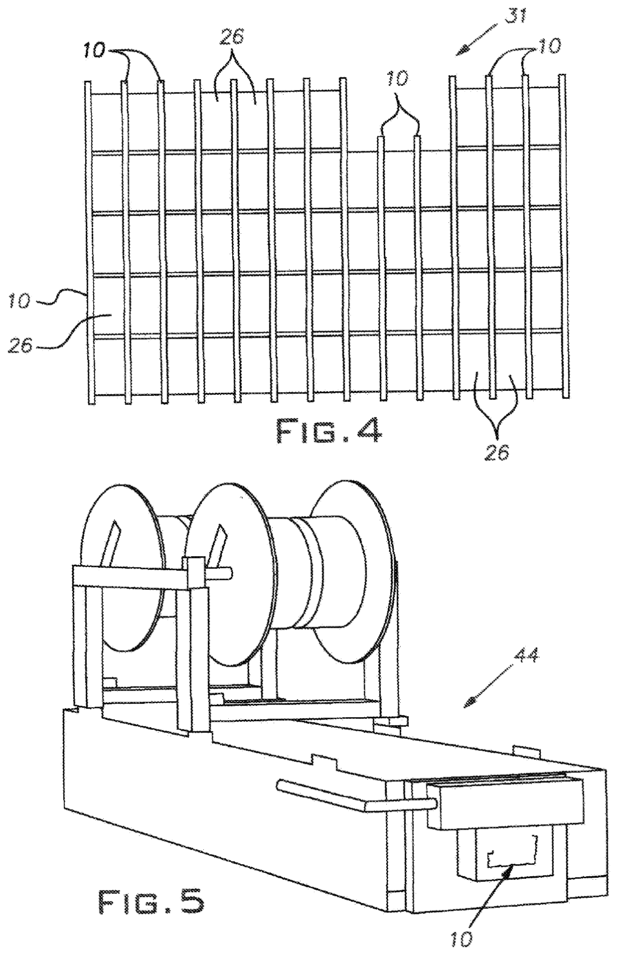
[0024]An elongated, longitudinally continuous rack channel 10 is shown in various figures. The rack channel 10, sometimes referred to simply as the channel 10, may be formed from a continuous strip of flat sheet metal stock. For example, the channel 10 may be fabricated of a strip stock such as 22 or 24 gauge steel coated with an alloy of 45% zinc and 55% aluminum marketed under the trademark GALVALUME®. Other metal stock such as galvanized steel or anodized aluminum of various gauges can be used. FIG. 1 illustrates the rack channel 10 in end view, the cross-section of the rack channel may have the same geometry, constant along the full length of the rack channel.

[0025]The channel 10 may have a generally rectangular cross-section with two generally upstanding legs or walls 11, 12 and a generally horizontal base or wall 13. The legs 11, 12 may be of unequal heights, a short leg 11 measuring approximately 3 inches in height and a longer leg 12 measuring approximately 6½ inches in heig...


PUM


Abstract

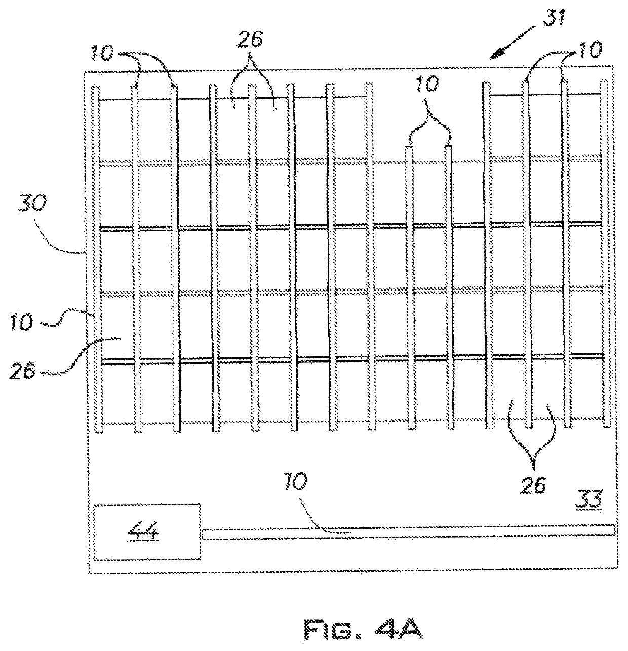
A method of installing on a horizontal or near-horizontal support surface a solar panel array including multiple solar panels may include, at the deployment site, fabricating from metal coil stock longitudinally continuous rack channels each having upstanding legs of different heights, locating the channels in parallel rows with a spacing determined by a width of the solar panels with interior spaces of the channels facing upwardly, weighing the channels down on the support surface by placing ballast in the channel spaces, and positioning the solar panels each with an edge supported by a high leg of one channel of the channels and an opposite edge supported by a low leg of an adjacent channel of the channels.

Description

CROSS-REFERENCE TO RELATED APPLICATIONS[0001]This is a continuation-in-part of U.S. Ser. No. 16 / 910,848, filed Jun. 24, 2020, which is a continuation-in-part of U.S. Ser. No. 16 / 269,663, filed Feb. 7, 2019, the entire disclosures of which are hereby incorporated by reference.BACKGROUND OF THE INVENTION[0002]The present disclosure relates to solar panel support systems particularly useful on flat or nearly flat roof and ground level fields.[0003]Conventional arrangements for supporting solar panels at a desired angle or orientation involved multiple parts including extrusions, bracketry, mounting tabs, and numerous fasteners requiring manual on-site assembly. Besides assembly, costs associated with these multiple component systems can include their separate purchase, handling, inventorying, shipping, and allowances for loss, particularly of small parts. Required on-site manual assembly of prior systems adds the risk of component damage and improper installation through human error, c...

Claims


Application Information

Patent Timeline
IPC IPC(8): H02S30/10H02S40/34
CPCH02S30/10H02S40/34H02S30/00H02S20/24H02S40/30Y02E10/50Y02B10/10Y02E10/47
Inventor SCIPIONE, DONALD S.MARTENS, ROB
Owner THE UNITED STATES AS REPRESENTED BY THE DEPARTMENT OF ENERGY
Features
  • R&D
  • Intellectual Property
  • Life Sciences
  • Materials
  • Tech Scout
  • Unparalleled Data Quality
  • Higher Quality Content
  • 60% Fewer Hallucinations
Learn More